Converting 3pt. brush hog to pull-type

Wondering if anyone has converted a 3-point brush hog to a pull-type. I was given a brush hog but all my tractors are non-3pt and dont want to install a 3pt set-up on the tractors. I've got a few ideas on how to do it but was wondering if anyone has did it before and has any pointers before I start the build.
Basiclly I'm going to add a set of wheels to the rear that can be raised either by a hydro cylinder or a hand adjust cylinder. Then add a togune and support for the pto. The brush hog is an old Ford model.
Ryan in Northern Michigan
 
Ryan:

I agree with Leland. You should have little trouble trading a small three point bush hog for a pull type.

Dean
 
I've had it sitting for 2 years and rarely come across someone witha pull-type. 99% of them up here are 3pt.
Ryan in Northern Michigan
 
(quoted from post at 11:23:34 01/20/10) I've had it sitting for 2 years and rarely come across someone witha pull-type. 99% of them up here are 3pt.
Ryan in Northern Michigan
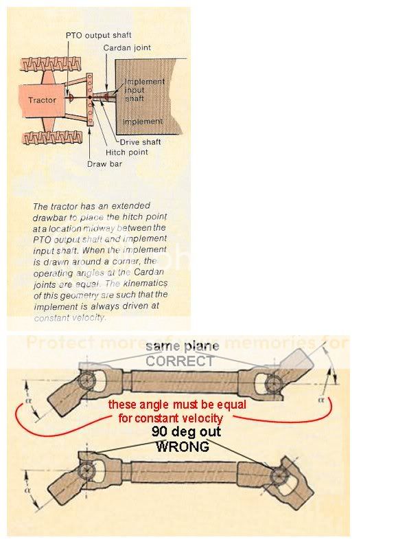
e careful that you don't do all that work and end up with a far less than satisfactory solution. If the hitch pivot point isn't mid way between the two u-joints, the velocity changes as the shaft make a revolution will chatter, beat the devil out of the whole PTO drive train and make you think (& rightly so) that it is about to self-destruct. I have one that some jake-leg built wrong that I have had for awhile with good intentions to fix right, but haven't ever run across the carrier bearing & shaft, so it may just sink into the earth. It is a piece of C as it is.
This gives the picture:
cardan_phasing_more.jpg
 
Sell the 3 point hog and then buy a pull type. In my neck of the woods a 3 point one will always bring more then a pull type does. Plus if you try to convert that 3 point to a pull type you will end up with a cobbled up mess and a machine that would not be worth much at all but as is should be worth $250 or more and you can buy a good pull type for that $$
 
I have a pull type Brush Hog. I like it its real heavy will cut anything and with the hydraulic lift on the rear wheels you can easily set the height for best cutting.

Mine has 700/14 tires on the back and the front hitch is made of two pipes that one fits into the other with holes about 2" apart for length adjustment.
Also there is an height adjustment on the end of the pipe with about 5 settings to raise or lower the front end.
If you want I can take some pics and send them to you.
The PTO shaft comes right off the gear box and goes straight to the PTO just like the original does. You will need the extra length for turns.

Walt
 
I dont cobble stuff up, if it cant be built to last, I wont do it. Went to school for welding/fab so I know something bout building stuff. Just wanted to get input/pointers from others that have done it.
 
Oh I understand what your saying since I was a welder and metal fab guy before I retired. But to do a good job would not be easy to do and in the long run it is cheaper to sell that one and buy what you need because it would be next to impossible to build a 3 point one into a pull one with out costing big $$$
 
In the late 1960's/early 1970's, my dad sold FMC SideWinder brand brush hogs. On the 5X5 and 6x6 series, the decks on the pull type and the 3-point were identical. The decks were shipped with whatever type hitch/axle specified, but one ordered as a pull type could be assembled as a 3-point, and vise-versa. Since I got the assignment of assembling most of the mower decks, I am 100% sure of this information.

The hitch for the pull type was a V-shape, with a tube serving as a "spreader" on the rear. The bottom hole on the V-type hitch mounted into the top mounting bracket hole on the front of the deck, IIRC. There was a link that connected one side of the hitch to the axle, so the V-shaped hitch could rotate its position as the axle rotated to raise or lower the deck. The axle appeared to be made of pipe, held to the deck by four loops made of shaped flat stock. The axle extended across the deck laterally, with approximately 18-24" rectangular extensions, to which spindles and automotive-style hubs were attached.

The factory-supplied lift mechanism was a rudimentary ratchet, which bolted to the deck and attached a threaded rod to the axle. This could be replaced with a hydraulic cylinder if the purchaser desired, but SideWinder didn't sell any cylinders or hoses for this purposes.

If I can find any of the old manuals--which include assembly instructions--in the collection I have from the shop, I'll try to post them on Photobucket or some other similar source, and then provide a link.
 
I"m with Armand on this; since you have the fabricating skills, I think your time might be better spent on building a 3-PH for the tractor you would most use with the bush hog. I have a tow type bush hog which I"m going to convert to 3-PH. The tow types are a bit of a PITA when working in tight quarters where you have to back up frequently. JMHO
 
Sure you can do it. First one I ever saw was built from scratch in our shop when I was a teen. One spring we got a new Montgomery Ward farm book and there was a pull type brush cutter in it. Dad and I opened the book and held it open with a couple pieces of iron and went to work. Built it out of stuff on the farm only cost was labor and welding rods. Put big springs on the axle and a plow lever to raise it up and set cutting hight. Neighbors all borrowed it as it was the only one around. Worked good. Still have it.
 

JMOR
Please correct me if I'm wrong but in the photo of the 2 pto shafts in a working situation if one turns right or left(drawn impl.) the angles will be similar to the shaft marked "WRONG". I can't vision how the photo marked "right" would happen on a drawn impl.

To keep u-joints from rattling the angles need to be the same degree. If distance of pivot point(hitch pin) is in the middle of u-joints the degree of angles will be the same provided the pto shaft on tractor is centered. This is why JD came out with the Equal Angle hitch before they went to Constant velocity joints.
 
(quoted from post at 08:16:38 01/21/10)
JMOR
Please correct me if I'm wrong but in the photo of the 2 pto shafts in a working situation if one turns right or left(drawn impl.) the angles will be similar to the shaft marked "WRONG". I can't vision how the photo marked "right" would happen on a drawn impl.

To keep u-joints from rattling the angles need to be the same degree. If distance of pivot point(hitch pin) is in the middle of u-joints the degree of angles will be the same provided the pto shaft on tractor is centered. This is why JD came out with the Equal Angle hitch before they went to Constant velocity joints.
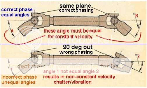
That is what I get for using artwork that is available instead of creating my own. There are two separate and distinct things being illustrated in that old drawing. 1) the equal angles at the two ends of the shaft, for best constant angular velocity and 2) a 90 degree incorrect phasing of the two u-joints.
Turning with a drawn implement, you stated,"To keep u-joints from rattling the angles need to be the same degree. If distance of pivot point(hitch pin) is in the middle of u-joints the degree of angles will be the same provided the pto shaft on tractor is centered. ", which is a FACT.
Further more the shaft/joint angles would be as in the old lower sketch, i.e., both turned down with equal angles, as you also said. I was just trying to show equal angles & did not have a drawing with everything correct in both the turning positions of the 2 joints AND the phasing. The old bottom sketch has correct turning joint positions, but INCORRECT phasing.
I hope all that makes sense.......I expect it does, I can tell from your statements that you know how all this works. You will like this better, as now I have both items correct in upper and both items wrong in lower, for a turning tractor/drawn implement.
cardan_phasing_angles.jpg

I sure do a lot of work for you...if I keep this up, someday I'll be good at Paint Shop Pro!
 

JMOR
Actually the correct answer isn't for me(maybe just to ease my mind) but for other readers. Some equipment operators probably didn't have a clue why their pto shafts vibrate while turning or how to correct it. Now they know.I suppose my questioning your statement comes from years of diagnosing problems as a JD service mngr.Thanks,Jim
 

We sell tractor parts! We have the parts you need to repair your tractor - the right parts. Our low prices and years of research make us your best choice when you need parts. Shop Online Today.

Back
Top