
You should upgrade or use an alternative browser.
- Thread starter FSA1953
- Start date
Thanks for the help
re you certain that you have a 12v generator & 12v regulator?(quoted from post at 06:58:53 05/04/22) I have 12.7 volts at battery with tractor off. When running I have 12.8 at battery shouldn't the volts be a little higher like 13-14? The generator is putting out 15-16 volts. The previous owner rewired it from 6 volt to 12 volt positive ground I'm trying to see if they wired everything correctly. Previous owner said battery would have to be jumped every couple of days so I'm thinking he missed a wire somewheres along the line for charging the battery. I can't seem to find and wiring diagram on showing what wires go where.
Thanks for the help
re terminals on your regulator arranged , left to right, as B-A-F or A-F-B ?(quoted from post at 07:42:34 05/04/22) Gentleman put brand new 12 volt generator
and regulator on have receipts when
purchased tractor. Generator is putting
out about 15-16 volts. Unless regulator is
bad. Idk

This post was edited by JMOR on 05/04/2022 at 09:34 am.
Steve@Advance
Well-known Member
Also be sure the base of the regulator is properly grounded.
The 30 amp amp meter is correct.
Here's a link to a past post on the subject with a diagram.
Wiring Diagram
K, you can "full field" the generator to obtain maximum output by connecting the Field terminal to the Arm terminal while running at speed. If still no rise at battery, temporarily connect Batt to Arm and look for battery voltage rise. The combined steps virtually eliminate the VR. Remove jumpers immediately if engine is stopped.(quoted from post at 16:06:50 05/04/22) Is A-F-B
This post was edited by JMOR on 05/04/2022 at 01:29 pm.
see what happens.
I attached a photo of and open spot with 4
looks like clips for something terminal
block? I looked for one but the don't look
like the original. Any idea where I can
get an original terminal block if that's
what goes there?
Thanks
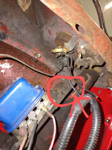
generator. There's nothing in that area of
the red circle if that's where the
terminal block goes. The wires you see are
cut off of the fuel gauge, ammeter the
only thing that works is the oil pressure
gauge. Should I just up the gauge of the
wires from the VR to generator?
Thanks
wouldn't change your wire gauges. The terminal block remained the same part for many Ford tractors & is available on YT site.(quoted from post at 12:35:40 05/06/22) Yes field is connected from VR to F on
generator. There's nothing in that area of
the red circle if that's where the
terminal block goes. The wires you see are
cut off of the fuel gauge, ammeter the
only thing that works is the oil pressure
gauge. Should I just up the gauge of the
wires from the VR to generator?
Thanks
https://www.yesterdaystractors.com/8NNN14448A_Terminal-Block_17470.htm
On a NAA (generation before yours) tractor, it was located as shown here: Perhaps others can tell you if same location or not.

hat is ok, as if good mechanical connections, gnd wire carries no current & if bad mechanical connections , it only carries a fraction of an amp for energizing VR coils, unless the gen were completely isolated, which seems unlikely.(quoted from post at 15:34:30 05/06/22) All wires going from the VR to generator are all 12 gauge wire and the ground wire to generator is a real small wire
This post was edited by JMOR on 05/06/2022 at 02:03 pm.
Facebook chat room and a gentleman said he
doesn't think the 12v generator might not
work with positive ground if so how'd the
6v generator work then. He said I may have
to switch everything to negative ground
for the generator to work is that true? If
so I'll need a diagram on which wire goes
where so I do it correctly.
Thanks
"V". He said, "he doesn't think"! Stay away from facebook OPINIONS. No, that is not correct. Only thing required for a generator to output one polarity or another is which way it is polarized. Once it has been connected and run in a system, it is in fact polarized. If polarized one way and then installed with a battery connected differently (i.e., battery pos gnd & gen polarized for NEG gnd, then the regulator has a good chance of being damaged. Illustration shows the POS to NEG clash at cut out contacts, where gen polarity is opposite battery polarity..(quoted from post at 09:14:56 05/07/22) I was just reading my response from my
Facebook chat room and a gentleman said he
doesn't think the 12v generator might not
work with positive ground if so how'd the
6v generator work then. He said I may have
to switch everything to negative ground
for the generator to work is that true? If
so I'll need a diagram on which wire goes
where so I do it correctly.
Thanks

This post was edited by JMOR on 05/07/2022 at 06:42 am.
he 3 post type requires either a ground or battery voltage to be applied to the small terminal to energize. Batt or Gnd depends on the solenoid part number. Most old Fords require a ground to be applied via neutral safety start switch.. Your tractor originally had a 4 terminal unit that needed gnd from neutral safety start switch AND battery voltage from the ignition switch. Later in life there came along another 4 terminal unit requiring batt voltage to one small terminal to activate and the second small terminal supplied battery voltage out to the ign coil during start to bypass the ballast resistor , thus compensating for the lower battery voltage during start. There are even % terminal solenoids.(quoted from post at 18:15:55 05/08/22) What's the difference between the 12v 3 post solenoid and the 4 post does it matter? I see some wiring diagrams showing the 3 post and some 4 post.
Thanks
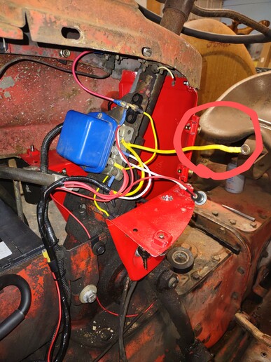
stop. The fat yellow that's circled does
that get hooked to the terminal block or
straight to the ammeter? Cause the
instructions that came with the wiring
harness shows it going to the terminal
block and another drawing I got from this
site shows it going to the ammeter and
another wire from the ammeter to the
terminal block. Which is correct? Also
when I do hook the ammeter up with two
wires separate wires the yellow wire to
the terminal block I get a discharge and
when I switched the separate wires I get a
charge this is with the tractor not
running. Should the ammeter always have
power to it with the key off or do I need
to add a third wire from the ammeter?
Similar threads
- Replies
- 12
- Views
- 470
- Replies
- 10
- Views
- 529
We sell tractor parts! We have the parts you need to repair your tractor - the right parts. Our low prices and years of research make us your best choice when you need parts. Shop Online Today.
Copyright © 1997-2024 Yesterday's Tractor Co.
All Rights Reserved. Reproduction of any part of this website, including design and content, without written permission is strictly prohibited. Trade Marks and Trade Names contained and used in this Website are those of others, and are used in this Website in a descriptive sense to refer to the products of others. Use of this Web site constitutes acceptance of our User Agreement and Privacy Policy TRADEMARK DISCLAIMER: Tradenames and Trademarks referred to within Yesterday's Tractor Co. products and within the Yesterday's Tractor Co. websites are the property of their respective trademark holders. None of these trademark holders are affiliated with Yesterday's Tractor Co., our products, or our website nor are we sponsored by them. John Deere and its logos are the registered trademarks of the John Deere Corporation. Agco, Agco Allis, White, Massey Ferguson and their logos are the registered trademarks of AGCO Corporation. Case, Case-IH, Farmall, International Harvester, New Holland and their logos are registered trademarks of CNH Global N.V.
Yesterday's Tractors - Antique Tractor Headquarters
Website Accessibility Policy