
New to the forum, so I appreciate any guidance. I am helping a family member repair the electrical system on their TO-30. It has a + ground, 12v system. When I first started working on this tractor, it was set up as a + ground. The entire wiring harness was deteriorated, so I have replaced it. New harness, resistor block, ignition switch, coil, points and condenser. I set up the battery with - ground, and the tractor would not start. No spark whatsoever. Switched back to + ground and the tractor started and ran beautifully. After turning it off (using the ignition switch), I started to smell an electrical odor. Found that the female blade insulation on one of the wires to the resistor block was melting (from the resistor block to the ampmeter), and the resistor block was extremely hot. I used glenmorebuckman's diagram (05-16-2021) as a guide, minus the #1 wire from the alternator to "I" on the keyswitch. The #2 wire from the alternator goes to one side of a resistor block (from TSC), and then from the other side of the resistor block to the amp meter. The coil (also from TSC) is a 6v, but states it can be used for 12v with an external resistor. Pretty sure I missed something pretty basic, but not seeing it.
You are using an out of date browser. It may not display this or other websites correctly.
You should upgrade or use an alternative browser.
You should upgrade or use an alternative browser.
- Thread starter ogreafmc
- Start date
old
Well-known Member
- Location
- Camdenton Missouri
A ballast resister will in fact get hot so hot it will burn your fingers if you touch it so normal
rvirgil_KS
Well-known Member
Does it have a positive or negative ground alternator? Most all common alternators were born negative ground but a few have been redone for positive ground.
If you switched polarity on the battery, even for a brief moment, you likely fried your alternator.
With positive ground the + post on coil goes to side of distributor. With negative ground the - side of the coil goes to distributor. On some tractors, with posts reversed they will be harder to start, but other than than the ground configuration should have no effect on starting.
Loose connections can cause heat build up.
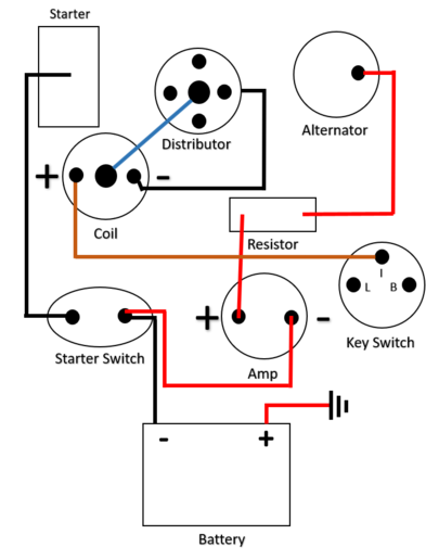
Thank you for your input. I do not know whether the alternator is + or - ground. The owner suffers from Parkinson's and cannot provide much info for that. I have included a quick wiring diagram for what I originaly found, and it has been returned to this set up after replacing alot of coroded wiring.
rom that diagram, it appears that you are trying to run the alternator output thru the resistor to charge the battery! Wrong! No wonder it gets hot. What about the other 2 alternator wires?(quoted from post at 12:50:27 04/25/22) Missed a wire from the B post on the ignition switch to the + side of the amp meter in my diagram.
Steve@Advance
Well-known Member
No, the diagram is not correct.
You can not reverse the polarity with an alternator! Unless it is a specialty
alternator set up for positive ground (99.9999% chance it is not), then it must
be wired for negative ground. Just for safety sake, check the battery to be
sure it is not charged backward, not likely, but it can happen.
Try this wiring diagram:
Conversion Wiring Diagram
RCP
Well-known Member
- Location
- Grove City Pa
I do not understand the resistor on the lead from the alternator to the ammeter, could it be a
diode? Usually the resistor is the on lead from the ignition switch to the distributor to cut the
amperage and extend the life of the points.
You should first confirm that the alternator is positive ground, this is not normal so I would be
surprised if it is. If it is actually negative ground the system needs to rewired to negative
ground. Is the alternator actually a single wire alternator that does not require being energized
from the key switch?
Take a bunch of pictures of the tractor, the wiring, the alternator, ignition switch lugs etc and
post them, there are a bunch of smart people on here that are willing to help.
J.Wondergem
Well-known Member
- Location
- Rockford, Mi.
If that alternator is working, I can see why the resister burnt up.
While most generators were + positive ground, most alternators are the opposite - negative ground, so when an alternator is used to replace a generator the ground polarity of the entire wiring needs to be change to negative ground. When a negative ground alternator is hooked up in a positive ground circuit, the one way diodes in the alternator get fried. By your diagram, if the resistor is fried the diodes are likely fried too.
If the resistor in your circuit diagram is intended to be a ballast resistor to use a 6 volt coil in a 12 volt circuit, the resistor needs to be on the wire between the ignition switch and the coil.
If the resistor in your circuit diagram is intended to be a ballast resistor to use a 6 volt coil in a 12 volt circuit, the resistor needs to be on the wire between the ignition switch and the coil.
old
Well-known Member
- Location
- Camdenton Missouri
Resister should not be in line with the alternator output and amp gauge so that is why it gets so hot
ctually, the incorrectly wired resistor may have saved the alternator from reverse polarity destruction, by limiting reverse current.(quoted from post at 13:12:56 04/25/22)rom that diagram, it appears that you are trying to run the alternator output thru the resistor to charge the battery! Wrong! No wonder it gets hot. What about the other 2 alternator wires?(quoted from post at 12:50:27 04/25/22) Missed a wire from the B post on the ignition switch to the + side of the amp meter in my diagram.
Steve@Advance
Well-known Member
I agree JMOR, the alternator is probably still good thanks to the resistor.
The resistor may have taken a hit though!
The resistor may have taken a hit though!
(quoted from post at 11:23:50 04/25/22) I do not understand the resistor on the lead from the alternator to the ammeter, could it be a
diode? Usually the resistor is the on lead from the ignition switch to the distributor to cut the
amperage and extend the life of the points.
You should first confirm that the alternator is positive ground, this is not normal so I would be
surprised if it is. If it is actually negative ground the system needs to rewired to negative
ground. Is the alternator actually a single wire alternator that does not require being energized
from the key switch?
Take a bunch of pictures of the tractor, the wiring, the alternator, ignition switch lugs etc and
post them, there are a bunch of smart people on here that are willing to help.
Sorry for the delay. Here are the photos.


This post was edited by ogreafmc on 04/26/2022 at 07:41 am.
There are enough things wrong , that rather than try to describe all the fixes, I recommend that you wire it as in this pictogram. Since your TO-30 uses stand alone coil , coil wiring will look more like the 8N diagram.


This post was edited by JMOR on 04/26/2022 at 08:55 am.
This post was edited by JMOR on 04/26/2022 at 08:55 am.
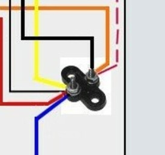
ust a terminal block....one always hot (energized) and the other is switched by ignition switch. Just a place to connect wires together.(quoted from post at 13:28:41 04/26/22) Thank you. I can see where they went wrong. Quick question, what is this?
<img src=https://www.yesterdaystractors.com/cvphotos/cvphoto124115.jpg>
BarnyardEngineering
Well-known Member
- Location
- Rochester, NY
(quoted from post at 11:20:26 04/26/22)
Thanks for the help. I will get together the items I need, and make the change this weekend. It was strange that with the wiring configuration in the photos, it would not start with a negative ground from the battery, but started immediately with a positive ground.
The coil is also polarity sensitive. If you had it wired up backwards for negative ground the spark may have been too weak for the engine to run. That's why switching the battery around made it run.
Unless you mean the engine would not even crank over with the starter. Then it had nothing to do with polarity and everything to do with bad connections at the battery. Swapping them around was enough to clean the connections so they would work.
This post was edited by BarnyardEngineering on 04/26/2022 at 11:34 am.
may have been" was a good choice of words. You will likely not ever know an answer. P.S., the coil output voltage will be reduced by one hundredth if polarity reversed, such as 9,900v versus 10,000v. HV polarity is different, but that matters not when cold. A slight bit when plug electrodes very hot, as electrons leave a hot surface a little easier the leaving a cold surface.(quoted from post at 14:46:03 04/26/22)
Engine cranked like a champ, but got no spark. Battery cables are new and tight, as were all of the wiring connections. As soon as I reversed the ground cable to "+", it immediately fired and ran beautifully.
f by chance the alternator is a positive ground, will it affect the diagram beyond switching the battery to + ground as well? NO.(quoted from post at 15:24:27 04/28/22) Will be heading down this weekend with some additional parts to mimic the 8N diagram. Thanks again for the help. If by chance the alternator is a positive ground, will it affect the diagram beyond switching the battery to + ground as well? Switch the leads on the coil?
Switch the leads on the coil? yes.....won't make a significant difference, but might as well do it right.
ou are welcome & happy that it worked out for you.(quoted from post at 11:34:19 05/05/22)
Used your diagram. Tractor runs like a champ!! Thanks to you and all who lent me their experience and expertise.
Similar threads
- Replies
- 11
- Views
- 439
- Replies
- 42
- Views
- 2K
We sell tractor parts! We have the parts you need to repair your tractor - the right parts. Our low prices and years of research make us your best choice when you need parts. Shop Online Today.
Copyright © 1997-2024 Yesterday's Tractor Co.
All Rights Reserved. Reproduction of any part of this website, including design and content, without written permission is strictly prohibited. Trade Marks and Trade Names contained and used in this Website are those of others, and are used in this Website in a descriptive sense to refer to the products of others. Use of this Web site constitutes acceptance of our User Agreement and Privacy Policy TRADEMARK DISCLAIMER: Tradenames and Trademarks referred to within Yesterday's Tractor Co. products and within the Yesterday's Tractor Co. websites are the property of their respective trademark holders. None of these trademark holders are affiliated with Yesterday's Tractor Co., our products, or our website nor are we sponsored by them. John Deere and its logos are the registered trademarks of the John Deere Corporation. Agco, Agco Allis, White, Massey Ferguson and their logos are the registered trademarks of AGCO Corporation. Case, Case-IH, Farmall, International Harvester, New Holland and their logos are registered trademarks of CNH Global N.V.
Yesterday's Tractors - Antique Tractor Headquarters
Website Accessibility Policy