The auction M part 3 Wiring


cvphoto96647.jpg


cvphoto96649.jpg

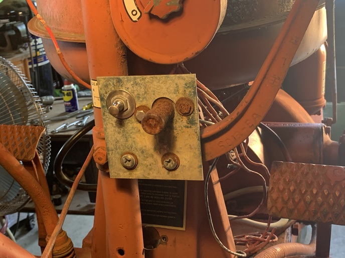
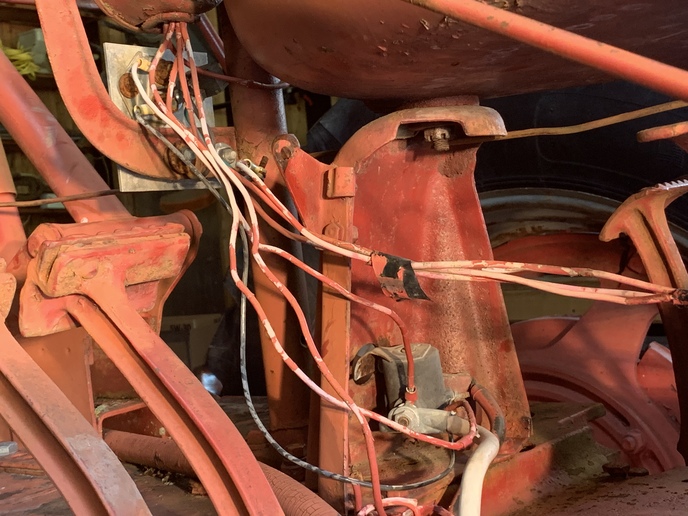
While were at a stand still waiting for parts to come in we decided to look at the wiring. I was going to try it the way it is but the more I look at it the less I like it. Im not sure why theres a solenoid wired in, other than my guess that the old owner was maybe a Ford guy and it made better sense to him? And I would call the general condition of the wire as poor. So Im going to rewire it. Shouldnt be a big deal but I would like it straight in my mind to I can show son. Please check me to see if I have this correct.
The kill switch to the mag is simply grounding it out so a single wire to the switch then to ground will work. Since were positive ground 6 volt wouldnt I be better off taking out the solenoid and sending the battery cables to the start button? Then the field wire from the generator can run to the volt meter then back to battery. And I have a new roll of 14 gauge automotive wire I plan to use for this do you think that is heavy enough? Thanks guys.
 
I'd use a solenoid like it has, I don't think you can buy a starter switch anymore that isn't junk.
 
I have restored several tractors and my advice would be to buy a complete new wiring harness. They are not expensive and all wires will be the right length, tagged to where they connect and will be the proper gauge. Several aftermarket people supply them, I have always used the guy from New York and they were always a perfect fit.
 
Well i would probably leave the solenoid (starter relay really) in place. As noted, finding a servicable high amp push button is difficult, and expensive if an industrial one (not stock looking) is put in place. The relay could be better placed closer to the the starter minimizing length from the battery to the starter, as well as losses in the cables. The cables should be 00gauge. (double aught) to function as needed to make an M spin. The next item is the generator. The light switch has the wrong decal on it. It should have L,H,D,B these stand for Low charge, High charge, Dim headlights, Bright Headlights. The switch is internally complex. It has two sections on one shaft. Section #1 is generator control. It has the function of grounding the F terminal of the generator either through a resistor, or directly to ground. The field on this A circuit charging system has the field getting its source inside the generator (a third brush) and grounding the field to make charging magnetism. So the light switch has 4 positions affecting the generator, and they are as follows. In L (turned Counterclockwise) the field ground goes through a wire wound resistor on the light switch, then to a switch contact, from there to the switch metal body to ground on the oval box, which grounds on the steering wheel support, which is grounded to the tractor platform. (all these pathways must be clean and shiny or it will not charge). In H position (one click CW) the Field is directly connected to the switch body, and to the same ground path. This allows the generator to put out its modest 12 amps into the battery to help keep it charged is the tractor is be stopped and started often, or in winter when used for shorter times. The amount of charge in amps is adjusted by moving the third brush closer to the fixed brush in the generator end plate. The D position, and B position also ground the gen the same as the H position, but that is to make enough electricity to run the lights, and charge the battery some.
The light control section of the switch is not grounded at all. It is supplied electricity from the 15 amp fuse (should be there) and sends electricity through a different wire wound resistor on the back of the switch in D position, and directly to the lights in the H position.
So do not hook electricity to the Field circuit. Bob M on this site has wiring diagrams for these components, use google to find it. Do not use one color of wire, and do use 12 gauge. 4 or 5 colors will suffice. Do solder terminals on the wires, then slide shrink tubing up on the terminal end to make them nice. Wire from the Generator A terminal to the ARM terminal on the cutout relay and the wire grom the cutout to the amp gauge and from the gauge to the start relat battery side, all should be red, and 10 gauge. I hope ths helps! Jim
 
Me I would definitely keep the solenoid and looks to me like just a little straitening up here and there and that deal will work. It is not all that bad.
 
The truth is Ive rewired my other 3 Farmall tractors and they all start fine and charge as the should and the lights work. So you would think Id have this down by now, but every time I get to the wiring my brain locks up and I have to talk it through again. I dont know why LOL. So yes this help a lot. Thank you.
 
In most responses to questions I must assume the need for a pretty comprehensive answer. I think I would make a small aluminum or stainless plate to mount a new marine grade push button, fuse. A little more tidy than that rusty sharp cornered plate. Jim
 
Comprehensive answers are usually the way to go. I can use this as a point of reference as I go to make sure Im setting this up correctly. And you never know there might be others out there having trouble that can read this and use it to get their projects going too. I was thinking the same thing on that plate. What I would like to do is get rid of it and use the holes that are already in the bracket to mount my switch and start button. Ill have to get that off and see if I can make it work.
 
Definitely keep the solenoid. I have mine mounted in the same place. I gave up on the foot switches as they don't last.
 
HUMMMmmmm , looks like it needs a couple hours of refit . I have made may new harnesses up over the years . and when done they look like they came out of a factory box. and sometimes even better.
 

We sell tractor parts! We have the parts you need to repair your tractor - the right parts. Our low prices and years of research make us your best choice when you need parts. Shop Online Today.

Back
Top