Goose
Well-known Member
I was doing some re-wiring on one of my H Farmalls this afternoon.
It all started when the tractor kept running the battery down. I traced that to the points being stuck together in the voltage regulator. I ran some fine sandpaper through the points and that seemed to fix it, but the wiring was horrible with some bare areas. Hence my project this afternoon. I decided to rewire the whole thing, except for a couple blue wires by the regulator that someone replaced recently.
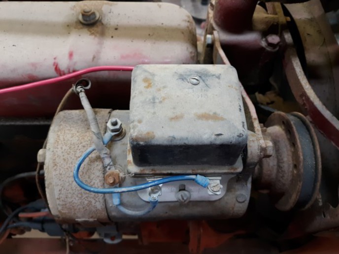
This is a 1941 H with the regulator on the generator.
Here's what stumped me. The regulator has three posts, and in the photo the oldest wire, bottom left with the tape on it, goes all the way back, and was simply taped off inside the ammeter box. I thought, "what the heck?"
So where is this wire supposed to go? I printed out several diagrams off the 'Net, so I'll play with it some more tomorrow. Since I bought this tractor several years ago, the ammeter has never really shown a charge, but on the other hand it's never shown a discharge or run the battery down. (Until the points stuck in the regulator).
I have another H, but it's a '51 with the regulator back by the starter.
It all started when the tractor kept running the battery down. I traced that to the points being stuck together in the voltage regulator. I ran some fine sandpaper through the points and that seemed to fix it, but the wiring was horrible with some bare areas. Hence my project this afternoon. I decided to rewire the whole thing, except for a couple blue wires by the regulator that someone replaced recently.
This is a 1941 H with the regulator on the generator.
Here's what stumped me. The regulator has three posts, and in the photo the oldest wire, bottom left with the tape on it, goes all the way back, and was simply taped off inside the ammeter box. I thought, "what the heck?"
So where is this wire supposed to go? I printed out several diagrams off the 'Net, so I'll play with it some more tomorrow. Since I bought this tractor several years ago, the ammeter has never really shown a charge, but on the other hand it's never shown a discharge or run the battery down. (Until the points stuck in the regulator).
I have another H, but it's a '51 with the regulator back by the starter.