Guido re: christie battery charger

ETxJohn

Member
Sorry that I haven't gotten back sooner. I've been working on a '79 Vette. I hope that you can give some help on this charger. I would hate to junk it if not much wrong with it.
The drawing is crude but correct as to where the wiring goes.
45076.jpg
 
That's an interesting circuit, especially the "shorted battery protection circuit".

What issue are you having, no AC output from the transformer, no DC output from the rectifier, or protection solenoid not closing, or no current flow to cables when protection solenoid is closed?
 
That's an interesting circuit, especially the "shorted battery protection circuit".

Bob, There is no DC output unless you turn voltage switch to 24v and push dead battery boost switch. Then you can turn back to 12v. output but it charges around 16.5-17 volts. I think part of that problem is that I have a temporary 1200uf cap in place of the needed 3300uf 35v cap. what I don't get is that no DC output to battery cables until put on 24v. and push switch. Somehow the solenoid needs to be energized at turn on.
Thanks
 
Yes, the 3300 mfd capacitor momentarily closes the solenoid when power is applied, then the solenoid is held closed by charging voltage.

First, install the correct capacitor and see if that fixes it. The current draw of the lamps chosen would obviously have an effect, as well.
 
If you happen to have three of the smaller caps, you could parallel them and give it a try, as well.
 
Hello ETxJohn,

It looks like the caps are getting the voltage too high. The original size would be all you need as it is charging. Bulbs were added trying to do the same thing. So I am thinking the cap is the original size. The solenoid is there to carry the extra momentary current with the heavy contacts,

Guido.
 
HMMMM, I don't see the lamp and caps as being part of a voltage regulating circuit, but rather as an RC circuit that initially engages the solenoid to charge the battery when the charger is powered up.

NOT sure why the charging voltage would be that high, but we don't know what range he's set it to, or how accurate his measurement is. It's certainly not unusual for a "boost charger" to put out that kind of voltage on it's high range.
 
Thanks guys,
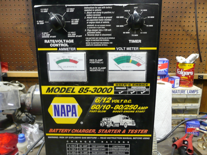
From what little info. that I can find, the charger appears to be approx. 40-50 amp max output. The 16.5 volt plus that it is showing is to a new, fully charged 12V battery. The needle to the amp meter is also broken so unsure of amp output. I plan to replace that and check. Maybe I'm over thinking this. It just seems strange the high output voltage and having to turn it to 24V and push dead battery boost to kick in solenoid. I checked these voltages on high with two different meters, so feel good on that. One more thing, I saw one of those solenoids on ebay listed as polarity protection so I don't know about that. Thanks
 
I know I'm an idiot for even suggesting this when it's obvious there is a capacitor in the existing circuit, but just try something to humor me:

Disconnect the capacitor and measure the output voltage of the charger on that fully charged 12V battery, and let me know what you get.

Lead acid chargers almost never have capacitive filtered outputs, the "R/C" of the battery averages the fullwave bridge or halfwave center taped output of the charger to what the battery sees as "full voltage" (be that 6, 12, or 24). I've seen and worked on battery chargers (bigger ones) that had capacitors, but they were in ferroresonant circuits, AKA constant voltage transformers. https://en.wikipedia.org/wiki/Voltage_regulator#Constant-voltage_transformer
 
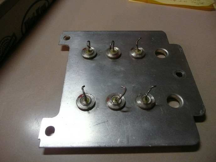
Here's a photo of part of the charger I'm slowly attacking. It's the rectifier panel and all diodes measure open in one direction and about
1.5 Meg in the opposite direction measured with a Fluke 73 III multimeter on the ohms position. That should mean all diodes are bad unless
my multimeter ohms-range battery isn't strong enough. I just put a new 9 V battery in the multimeter
a150452.jpg
 
Hello 55 50 Ron,

Your meter has a diode tester setting right next to the ohm's range, use that to get a good read on the diodes. I studied the circuit again, and I would like to see what the a/c input is on the diodes. Seems that the capacitors have increased the output,
but I can't see how by the circuit though,

Guido.
 

We sell tractor parts! We have the parts you need to repair your tractor - the right parts. Our low prices and years of research make us your best choice when you need parts. Shop Online Today.

Back
Top