Nuffield Universal 3 Wiring Overhaul schematic

KlemKadid

New User
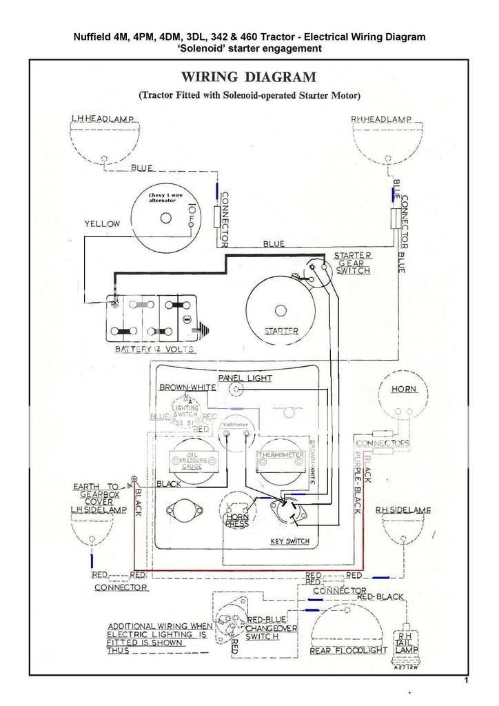
Could someone more experienced then I look at this wiring diagram and tell me if they can spot any problems with it? Im fairly new when it comes to wiring and dont feel like lighting the ol girl up one day cause of inexperience.

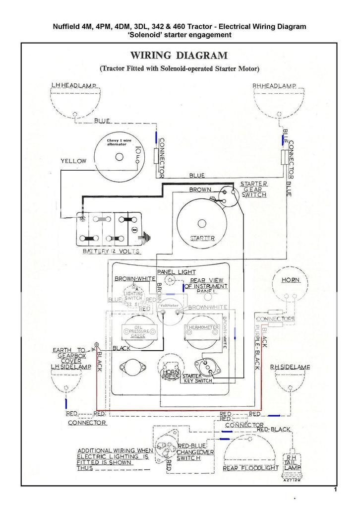
Blue dashes are line fuses

the red wire is one im not too sure about as it was connected to the old control box before the gearbox ground

Im hoping to install a voltmeter instead of an ammeter

alternators a delco remy 1 wire alternator

tractors a Nuffield Universal 3


Ive also been advised to install a kill switch near the battery terminal, but considering the whole thing is turned on via an ignition key switch, would I need to?

thanks

Wiring%20diagram%20Nuffield%204DM%20solenoid%20starter-page-001_6.jpg
 
The wiring diagram is for a tractor with a generator and a regulator for use with a generator. With the wiring diagram shown the tractor is equipped with voltmeter. Can you check that? I see the tractor is already negative ground so you will not need to change that. You have e-mail and or a phone number. I prefer a 3 wire unit,
 

Im not quite sure on what you mean by

The wiring diagram is for a tractor with a generator and a regulator for use with a generator.

the original wiring diagram and tractor had that kind of setup, dynamo with a control box, but theres an alternator put in now, as for a starter w/ selinoid.

the tractor at this moment has no wiring at all, nor guages, I know the original Nuffield 3 had an ammeter, but im not sure if I want to go with that system or not, but im not sure if I have too much going through the voltmeter in this diagram so any advice there would be helpful
 
A voltmeter is wired in parallel. Volts are the pressure in the system. Output (amps) does not flow through the voltmeter. Amp meters measure current flow. The current flows through an ammeter. FYI for it would be wise to use at least a 10 gauge wire from your ammeter to the battery to handle the output safely or through the ammeter if you go back to using an ammeter. You have e-mail or a phone number?
 
(quoted from post at 13:09:10 01/03/16) A voltmeter is wired in parallel. Volts are the pressure in the system. Output (amps) does not flow through the voltmeter. Amp meters measure current flow. The current flows through an ammeter. FYI for it would be wise to use at least a 10 gauge wire from your ammeter to the battery to handle the output safely or through the ammeter if you go back to using an ammeter. You have e-mail or a phone number?

So when wiring the volt meter, would it be before or after the ignition switch, its a 3 point switch fyi

i have a email, but i cant PM you for some reason and am not inclined to post it in the open
 
The problems I see:

1. The brown wire on the starter solenoid. This terminal is not a ground. It energizes the starter, should
wire from the "start" position of the ignition switch, or a separate start button. It must also have a
neutral safety switch or some mechanical interlock to prevent starting in gear.

2. There is no engine kill circuit. Being a diesel there may only be a kill lever, but there may be a run
solenoid. As the diagram is shown, turning the ignition switch off will not stop the engine.

3. This is just a preventive recommendation, move the yellow alternator wire to the starter connection.
This will get it away from the corrosive battery.

The question about the red wire...

Are you asking about the wire that is colored red in the drawing? If so, that is the horn ground.

Or are you asking about the wire circuit labeled red in the diagram? That circuit powers the side marker
lamps and the switch for the tail light and rear flood light.

For wire sizes, I would recommend the yellow wire from the alternator and the wire from the starter to the
ignition switch be # 10. The rest can be #14 or #16 stranded.
 
(quoted from post at 15:26:33 01/03/16) The problems I see:

1. The brown wire on the starter solenoid. This terminal is not a ground. It energizes the starter, should
wire from the "start" position of the ignition switch, or a separate start button. It must also have a
neutral safety switch or some mechanical interlock to prevent starting in gear.

2. There is no engine kill circuit. Being a diesel there may only be a kill lever, but there may be a run
solenoid. As the diagram is shown, turning the ignition switch off will not stop the engine.

3. This is just a preventive recommendation, move the yellow alternator wire to the starter connection.
This will get it away from the corrosive battery.

The question about the red wire...

Are you asking about the wire that is colored red in the drawing? If so, that is the horn ground.

Or are you asking about the wire circuit labeled red in the diagram? That circuit powers the side marker
lamps and the switch for the tail light and rear flood light.

For wire sizes, I would recommend the yellow wire from the alternator and the wire from the starter to the
ignition switch be # 10. The rest can be #14 or #16 stranded.


Engine kill switch is a mechanical type that hooks up to a pull lever on the dash that hooks up to a lever on the engine.

I was also told by someone else that theres too much power running through the volt meter, so i altered the schematic according to that and what you told me.

I think my main issue now is how to connect the voltguage in parrellel to the system, would I hook up the positive in with all the other implements on the other side of the ignition, or does it go somewhere else?

advice?

Wiring%20diagram%20Nuffield%204DM%20solenoid%20starter-page-001_7.jpg
 
The volt meter will work as shown. Unlike an ampmeter, the volt meter draws minuscule amperage, so it can
wire anywhere down stream of the ignition switch.

The start circuit will work now, but still no neutral switch. I suspect there is one somewhere, usually on
top of the transmission housing. Don't want to be a pest, but can't stress enough the importance of the
neutral switch! I know you will be careful, but the problem is the beasts we build out live us... Who will be
operating it a few years from now?
 
One other observation, there are way too many fuses! Don't want any more sources of problems on a tractor than is necessary. Since the running and charging are not critical to the switched circuitry, I would narrow down the fuses to the 3 circuits coming off the ignition switch.
 

We sell tractor parts! We have the parts you need to repair your tractor - the right parts. Our low prices and years of research make us your best choice when you need parts. Shop Online Today.

Back
Top