John T and Buick-Deere - coils with built-in resistors

JDemaris

Well-known Member
Just in case the post I put in the restoration
thread gets lost in space.

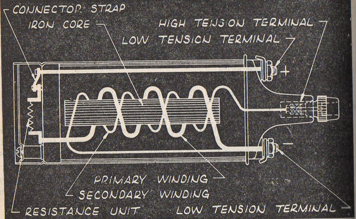
Back in the "old days' of autos, many companies
used ignition coils with built in ballast
resistors and sometimes built in capacitors.
Delco, Atwater-Kent, and Remy certainly had
them. In the 1930s - Delco listed four
different type coils.

#1 ROUND TYPE WITH STRAW-COLORED SHELL - has no
condensor or resistor built in.

#2 ROUND TYPE WITH BLACK SHELL - built in
resistance unit but no condensor

#3 D-TYPE WITH BAKELITE SHELL - resistance unit
built into top of coil can.

#4 d-TYPE WITH BLACK SHELL - condensor and
resistance until built into end of coil can.
a173837.jpg

a173838.jpg
 
A BIG THANKS JD, My old memory was right indeed surprise lol. I thought I saw a picture once with an older car coil that contained a ballast resistor inside the can, and it looks like my memory was also correct regarding that noticeable ring separation in the can (something I've never seen on any old tractor coil). Of course, that was back in the thirties and NOT in any old tractor coil (the kind most discussed on this antique tractor forum) I ever saw or recall from the thirties and up. Prior to then many tractors used Magnetos instead of battery powered coil ignitions. Now watch somebody post a picture of a thirties or forties vintage tractor coil like that coil above lol lol NEVER SAY NEVER

I learned to NEVER SAY NEVER AND NEVER SAY ALWAYS on here and try to choose my words which is I why I often (not every time) say when telling people coils DO NOT have an internal discrete stand alone ballast resistor, I'm talking about typical old tractor coils which remains true I believe until proven otherwise.

Thanks again, fun and informative post and as I posted recently, I don't consider any post or story useless, right or wrong, but whose to judge that NOT MEEEEEEEEEEE lol.

John T Always love to learn something new THANKS AGAIN JD
 
From an electrical point of view, it makes absolutely no difference if the resistor is a separate device inside the coil, the primary coil winding itself (using small gauge wire) or a device separate from the coil. Coil energy will be exactly the same, assuming resistance and inductance are the same.

Obviously it's a lot cheaper to use the primary coil winding for the "internal resistor" rather than a discrete device. I assume the older coils such as in your illustration used a separate resistor to keep heat away from the coil windings.
 
Chrysler used version of that in the 50s. It had a resister that varied resistance with temperature . Higher temp, higher resistance. That was used instead of the normal start circuit bypass to get high voltage when starting, lower when running.

I made the mistake one time of using one of those during and engine swap. But, my chassis wiring had a firewall mounted ballast. Took a while to find out why it wouldn't start when really cold, and never really ran well when hot!
 
Good info, thanks for posting it. I'm aware of and have used and worked with that Chrysler system. Of course, its a EXTERNAL BALLAST that has "thermistor" characteristics, NOT any internal inside the coil can or anything like that. Some later units had two ballasts side by side on a big block as I recall. I used to use them when I modified my marine engine ignitions, those were fun days.

Fun chat, thanks and take care

John T
 
I recently bought a coil with a built in resistor for my Kohler K series engine.

The external resistors in cars came about to boost spark during starting. I you have a coil/destributor type car and it starts but dies immediately after releasing the key it is the resistor open.
 
For energy stored in the inductance, wL = 1/2 LIexp2 where the energy is taken for the existing current at the instant the points open (L di/dt). The resistor value, inductor primary resistance, and the battery voltage set the I (amperage) part for a given L (inductance) and point dwell (time the points are closed causing currint to flow through the coil), regardless of the location of the resistor (inside or outside the coil's case).

The resistor is sized to control the current through the points to around 4-5 amperes (value derived from MF service manual).

The coil cares not if 6 or 12 volts is running the circuit. It reacts to current. The secondary of the coil (actually high voltage transformer) rises as fast as the leakage inductance of the coil will allow up to a max of around 18kv (prior to electronic ignitions) or to whatever part of that is needed to make the plug gap break over.

The purpose of the capacitor (condenser...condenses the voltage spike) across the points is to limit the rate of rise and thus ultimate value of the inductive kick generated across the points when they open to reduce pitting and provide for longer point contact life. I think that by eliminating, or at least reducing the sparking you reduce the O3 (ozone) that would be generated in a spark which helps to keep the point material where it was initially located, not on the other contact, aka pitting.

It has been rumored that when 12v systems became common a lot of 6v coils were used with the internal resistor making a 12v coil. But JD's pics may knock the wind out of some of that.

I remember Ford cars having the external resistor bypassed for ease of starting.

Oh well. That's the way I remember it and it has been awhile.

Mark
 

We sell tractor parts! We have the parts you need to repair your tractor - the right parts. Our low prices and years of research make us your best choice when you need parts. Shop Online Today.

Back
Top