
You should upgrade or use an alternative browser.
- Thread starter Ramhoff
- Start date
think you know the answer..........wiring isn't all right. But since I can't see what you have done from here, only you can determine what is wired incorrectly. Now, I you can accurately draw out your wiring & post it or e-mail it, I can then see what is wrong.(quoted from post at 13:37:55 06/02/11) Bought conversion kit from yesterdays tractors Tractor ran before conversion now wont start. Retraced wiring all seems right, but coil has power at all times. Key on and off. Please help. Work to do and no tractor.
emove the two wires on the key switch.......separated there should be no coil power...........touch together & should have coil power.(quoted from post at 17:04:14 06/02/11) I REALIZE there is something wrong with wiring or I wouldn be asking for help but all the wiring that I did when I replaced the 6 volt with the 12 volt is exactly what is shown on diagram. The only thing I can think could be wrong is it is not the original key switch on the tractor. My coil wire (brown) goes from coil to added resister and then to the top left original resister block post. Ignition switch has more than just the two wires that are on original. I did not put this switch in bought it that way.
Highlighted path is all that is necessary to power coil. Colors may not match your harness.
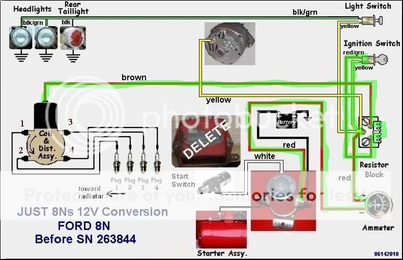
Look at JMOR's drawing. find coil, trace wire from coil to ballast resistor thru reistor then to the ignition switch then to the terminal block which ties it in the line form the battery . In other words everything he high lighted in green.(quoted from post at 07:35:10 06/03/11) The only thing i see different on the wiring diagram you sent me is that my alt wire goes directly to ampmeter and not to resister block first. I will change this. Should the coil wire attach to ignition switch somewhere? Some of the diagrams i have looked at show it hooked into it.
e sure one of ammeter terminals has only one connection and that is to the battery+ via the battery cable to solenoid.(quoted from post at 18:35:10 06/02/11) The only thing i see different on the wiring diagram you sent me is that my alt wire goes directly to ampmeter and not to resister block first. I will change this. Should the coil wire attach to ignition switch somewhere? Some of the diagrams i have looked at show it hooked into it.
It would be easier if you got rid of the three terminal switch and got one with two terminal or wires to it. If you have a test meter remove all wires from stirch and with stitch off, check for continuitry from terminal to terminal. there should be none. With the switch in the on position do the same. with it on you should have continuity from the battery terminal to the ignition.(quoted from post at 00:19:58 06/04/11) Got the wiring for coil the way you said to and took wires off ignition switch no juice to coil at all. I beleive it is wiring on switch thats my problem. Switch has three posts Batt. Assc. and Ign. No assc. is for lights but where does wire go for the other two. At the present time there are two wires coming off the Ign they were both hooked into existing resister and for some reason unknown to me Batt wire was cut off. Shouldn I just have one off Ign and where does this go? What gauge wire should come off Batt and where should it go?
JMOR's drawing show the resistor block. Only the two terminals on the right side of drawing are for the resistor. the third one is just a place to hook all the other wire together.
Think of an electridal circuit as plumbing. electrical current flows thur wire as water thur pipes.
Would you not think that if the switch is marked batt, ignition that that might be where the wires should run too?
(quoted from post at 08:40:41 06/03/11)It would be easier if you got rid of the three terminal switch and got one with two terminal or wires to it. If you have a test meter remove all wires from stirch and with stitch off, check for continuitry from terminal to terminal. there should be none. With the switch in the on position do the same. with it on you should have continuity from the battery terminal to the ignition.(quoted from post at 00:19:58 06/04/11) Got the wiring for coil the way you said to and took wires off ignition switch no juice to coil at all. I beleive it is wiring on switch thats my problem. Switch has three posts Batt. Assc. and Ign. No assc. is for lights but where does wire go for the other two. At the present time there are two wires coming off the Ign they were both hooked into existing resister and for some reason unknown to me Batt wire was cut off. Shouldn I just have one off Ign and where does this go? What gauge wire should come off Batt and where should it go?
JMOR's drawing show the resistor block. Only the two terminals on the right side of drawing are for the resistor. the third one is just a place to hook all the other wire together.
Think of an electridal circuit as plumbing. electrical current flows thur wire as water thur pipes.
Would you not think that if the switch is marked batt, ignition that that might be where the wires should run too?
LOL I can see a problem here.....what happens if the person don't know squat about plumbing???????
Rick
(quoted from post at 08:25:52 06/04/11)(quoted from post at 08:40:41 06/03/11)It would be easier if you got rid of the three terminal switch and got one with two terminal or wires to it. If you have a test meter remove all wires from stirch and with stitch off, check for continuitry from terminal to terminal. there should be none. With the switch in the on position do the same. with it on you should have continuity from the battery terminal to the ignition.(quoted from post at 00:19:58 06/04/11) Got the wiring for coil the way you said to and took wires off ignition switch no juice to coil at all. I beleive it is wiring on switch thats my problem. Switch has three posts Batt. Assc. and Ign. No assc. is for lights but where does wire go for the other two. At the present time there are two wires coming off the Ign they were both hooked into existing resister and for some reason unknown to me Batt wire was cut off. Shouldn I just have one off Ign and where does this go? What gauge wire should come off Batt and where should it go?
JMOR's drawing show the resistor block. Only the two terminals on the right side of drawing are for the resistor. the third one is just a place to hook all the other wire together.
Think of an electridal circuit as plumbing. electrical current flows thur wire as water thur pipes.
Would you not think that if the switch is marked batt, ignition that that might be where the wires should run too?
LOL I can see a problem here.....what happens if the person don't know squat about plumbing???????
Rick
Well , in that case the person might leave plumbing and electrity alone!! :lol: :lol:
Both of my 8N's are 6 volts and they run just fine also, but each to his own!(quoted from post at 19:27:05 06/04/11) My 640 started fine and worked for an hour this am Still 6 volt.
Similar threads
- Replies
- 13
- Views
- 402
- Replies
- 15
- Views
- 1K
We sell tractor parts! We have the parts you need to repair your tractor - the right parts. Our low prices and years of research make us your best choice when you need parts. Shop Online Today.
Copyright © 1997-2024 Yesterday's Tractor Co.
All Rights Reserved. Reproduction of any part of this website, including design and content, without written permission is strictly prohibited. Trade Marks and Trade Names contained and used in this Website are those of others, and are used in this Website in a descriptive sense to refer to the products of others. Use of this Web site constitutes acceptance of our User Agreement and Privacy Policy TRADEMARK DISCLAIMER: Tradenames and Trademarks referred to within Yesterday's Tractor Co. products and within the Yesterday's Tractor Co. websites are the property of their respective trademark holders. None of these trademark holders are affiliated with Yesterday's Tractor Co., our products, or our website nor are we sponsored by them. John Deere and its logos are the registered trademarks of the John Deere Corporation. Agco, Agco Allis, White, Massey Ferguson and their logos are the registered trademarks of AGCO Corporation. Case, Case-IH, Farmall, International Harvester, New Holland and their logos are registered trademarks of CNH Global N.V.
Yesterday's Tractors - Antique Tractor Headquarters
Website Accessibility Policy