12 volt conversion seems to have failed

Anonymous-0

Well-known Member
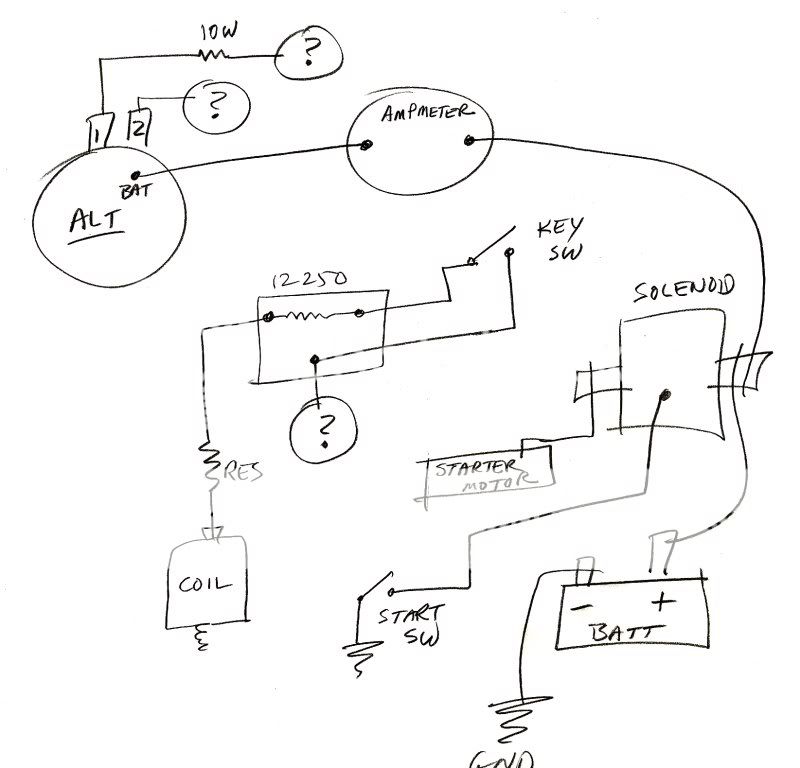
I got the complete kit: 12v coil, correct alt. pulley, resistor, brackets, wiring harness etc.

I wired as per the instuctors. I wasnt sure on a few things, but did the best I could.

The few things:
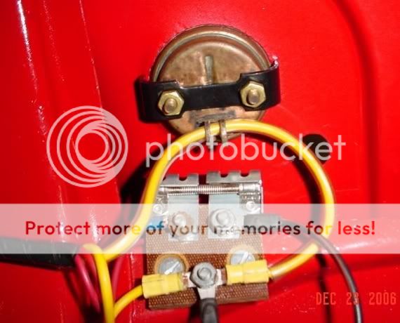
1. the existing ammeter wire went thru a metal circel not hard wired to the left and right screws (assume the old way used induction) thus as per instructions, used the left and right screws.
2. The kit came with a 12v coil and a resistor. Instructions stated use of the resistor IF NEEDED. So I figured I needed it, and put it per instructions..in-line between the coil and the left post of the existing resistor. I mounted it under the ammeter on the firewall.

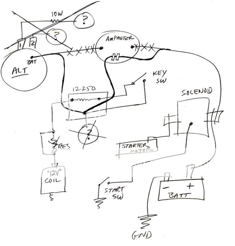
When I first tried to start it, there was a few sparks in the vicinity of the ammeter/new resistor. But she started anyway. I ran her for a little while...5 min, then drove her down to the barn (100 yds away). Then I plugged her in(water heater..she doesnt start very well in the cold weather...THUS THE MAIN REASON I WENT TO THE 12 VOLT SYSTEM).

By the way, while I had her opened up, replaced the rotar and the consensor, didnt mess with the points.

The next day...nothing...zip...nada. She turns over fine. Im thinking its got to be no gas or no spark. The gas should be fine, thus no spark.

Thoughts???

Brett
 
If you still have the original induction ammeter and you wired to the left and right screws instead of going through the loop, it's probably grounded - thus the sparks in that area. You only wire to the screws on the newer style ammeters where the posts are insulated from ground. Just a guess - I have both, but am too lazy to go down to the barn and check'em out in this weather.....
 
Front-mount distributor with "square-can coil" or "side-mount" distributor with "round-can coil"?

If a "front-mount", what is working the best for folks with the current "crop" of imported coils is to LEAVE THE OEM BALLAST RESISTOR IN PLACE and NOT add additional resistance. (If your's is bad/sparking, replace it with an OEM-style unit.)

If a "round-can coil" for a "side-mount" distributor, simply be sure the coil is labeled "12-Volts" and does NOT state "external resistance required, then eliminate the OEM and any additional ballast resistors.

Unless I mis-read your post, and you DO state what distributor you have, the guys giving you advice without knowing what setup you have are simply blowing smoke out their "posteriors"!

(Yes I know a "side-mount" WOULDN'T have an OEM resistor on the backside of the dash, but with all the stories that come up on here about parts/engines/rearends being swapped about, it's best to know all the facts before telling folks what they should do!)
 
go to www.ytag.com/articles/artint195.htm

This is a step by step 12-volt conversion. While it mentions Farmall & Super M tractors. This is the one I used for converting my 1950 8N with side distributer, alternator,etc. I did use the 10 watt resister instead of the warning light mentioned in the wiring diagram
 
(quoted from post at 19:02:23 12/16/08) Front-mount distributor with "square-can coil" or "side-mount" distributor with "round-can coil"?

If a "front-mount", what is working the best for folks with the current "crop" of imported coils is to LEAVE THE OEM BALLAST RESISTOR IN PLACE and NOT add additional resistance. (If your's is bad/sparking, replace it with an OEM-style unit.)

If a "round-can coil" for a "side-mount" distributor, simply be sure the coil is labeled "12-Volts" and does NOT state "external resistance required, then eliminate the OEM and any additional ballast resistors.

Unless I mis-read your post, and you DO state what distributor you have, the guys giving you advice without knowing what setup you have are simply blowing smoke out their "posteriors"!

(Yes I know a "side-mount" WOULDN'T have an OEM resistor on the backside of the dash, but with all the stories that come up on here about parts/engines/rearends being swapped about, it's best to know all the facts before telling folks what they should do!)
I'm pretty much on board with you Bob, but if he really wired to the old original loop style ammeter mounting screws, there should be the aformentioned sparks & maybe fire & smoke too. WOW!
 
not really too concerned bout the ammeter....not running around a bunch. If I start to drain..ill find out.

So if i can eliminate the ammeter = no problem.
 
Again, I have a front end distributer and coil. The coil that came with the kit is suppose be a 12volt. I'm using the OEM resistor thats mounted on the fire wall (3 post- the center being the junction post). and added per instructions the inline resistor between the coil and the OEM resistor.

Here is the wiring per instructions:

Key = red wire to right post on existing resistor, the other wire to the center junction resistor post on the resistor

battery = front post on solenoid, other grounded on frame

floor starter = white wire to side post of solenoid

solenoid = red wire from front post (with the battery lead) to the right ammeter post

alternator = red wire to left ammeter post

coil = brown wire to new resistor mounted on fire wall

new resistor = orange wire to left post on existing OEM resistor on firewall

whew...hope that clears stuff up...and got 6 inches of snow that needs moving...opps


thanks for the reply's

Brett
 
and by the way...why would it run going down to the barn and not start the next day??? Did i burn something up?

Brett
 
Brett.......the original ammeter had "donut" to feed the battery charging wire thru. It has 2-posts for mounting that are each GROUND. Modern replacement ammeters have 2-INSULATED posts to mount the ammeter and using their instructions to wire the battery charge (red wire to ammeter left post) to an original ammeter is directly SHORTING yer new alternator output to ground.

You do know what happens when you short yer alternator output to ground, don't you? You let the "smoke" out of yer alternator and it QUITS working. You doubt? Take yer alternator in to enny autoparts store for a "free" test. (and weap, 'cuz yer a clueless clutch)

Iff'n yer new 1-terminal squarecan ignition coil is truly the modern 12-volt squarecan ignition coil (it will say on the box) then you DO NOT NEED extra resistor they sent you. You MUST USE the original "infamous ballast resistor" with the new 12-volt squarecan ignition coil BUT NOT the extra resistor. Do you understand that???

Remember, 12v alternators DEMAND NEGATIVE ground, while yer original 6v genny was positive ground. 3-terminal starter solenoid don't care positive or negative ground; starter solenoid don't care 6-or-12v..........respectfully, Dell, a 12v advocate for the right reasons. That said, I haven't found the right reason for my eazy starting 6-volt 52-8N and I know how to do it right the first time. Infact, I know 8-ways to do it right and they all work.
 
(quoted from post at 23:48:50 12/16/08) and by the way...why would it run going down to the barn and not start the next day??? Did i burn something up?

Brett
Probably. I strongly suspect a short at the ammeter. Does your ammeter look like this?
loop_amp_with_res.jpg


If yes and you connected wires to the two studs/nuts, then you connected both the alternator output as well as the battery positive to ground. If that is the case, I do not know why wires didn't burn nor how it could have ran. Maybe too rusty/dirty to make a good ground connection???
Of course, given the question mark at 3rd terminal of 12250 resistor block, it is impossible to say what mighty be. Where does that wire go??
There are also two other ? marks at the alternator that you also failed to address. Where are those two connected??
q_wire.jpg
[/img]
 
your tractor looks MUCH better then mine!!

Yes the ammeter is like that. Using the 2 posts (nuts)...i got rid of the wire thru the loop...dont know where it came from or where it went. Thats the first point. Well is guess it goes to the middle post of the OEM resistor...per your pic.

Key switch...the first goes to the right post as per your drawing...then 2nd goes to the middle post(junction post) on the OEM resistor. thus answers your orther ?

coil goes thru a resistor to left post on OEM resistor..also as per your drawing

the alternater only had 1 lead...12 volt alt...nut on the back..for red lead...goes to the left ammeter post. It doesnt have any other leads.

thanks for your comments

Brett
 
(quoted from post at 01:49:45 12/17/08) your tractor looks MUCH better then mine!!

Yes the ammeter is like that. Using the 2 posts (nuts)...i got rid of the wire thru the loop...dont know where it came from or where it went. Thats the first point. Well is guess it goes to the middle post of the OEM resistor...per your pic.

Key switch...the first goes to the right post as per your drawing...then 2nd goes to the middle post(junction post) on the OEM resistor. thus answers your orther ?

coil goes thru a resistor to left post on OEM resistor..also as per your drawing

the alternater only had 1 lead...12 volt alt...nut on the back..for red lead...goes to the left ammeter post. It doesnt have any other leads.

thanks for your comments

Brett
OK, Brett, remove the wires from the "terminals" (really mounting bolts) and re-establish the loop as I show in the drawing. You end up with 3 wires on the 3rd terminal of resistor block(12250). If you got a new "12v" coil in your kit, you can probably skip the extra resistor. If it starts & runs fine with it in there, leave it, otherwise, jumper it or remove it & replace it with a piece of wire.
q_wire_2.jpg


P.S. I wish my tractor looked that nice, too. I commandeered the ammeter pix from someone else.
 

We sell tractor parts! We have the parts you need to repair your tractor - the right parts. Our low prices and years of research make us your best choice when you need parts. Shop Online Today.

Back
Top