GTB Alternator/External Regulator Circuit

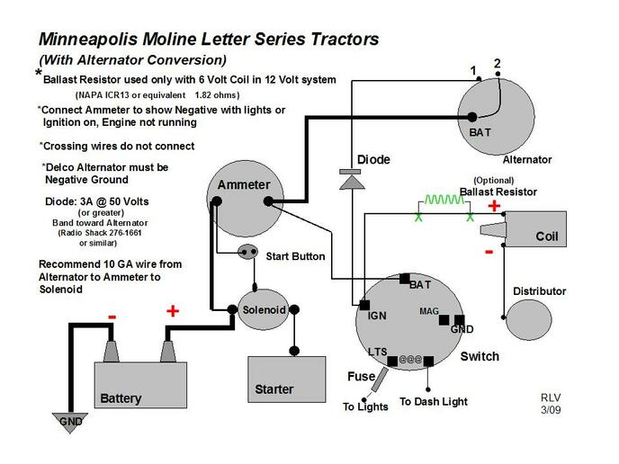
Hey folks, were putting the finishing touches on my Fathers GTB and are down to the wiring now. At some point it was converted to a two wire alternator (Delco 10DN) with an external regulator. The wiring was a rats nest so were starting from scratch here.
I cant for the life of me find a schematic that details how to wire in the alternator/voltage regulator with the remainder of the original equipment.
Could someone lend us a hand. If you need some more info just let me know.
Thanks.
 
If it were mine I would seriously consider changing to a Delco 10SI internal regulated alternator. Simpler and easier to troubleshoot in the future. It should mount the same as your 10DN

This diagram might help.
cvphoto160816.jpg
 
Here's a simple diagram of how to wire the 10DN and voltage regulator.

J5yY9me.jpg


Instead of running the output direct to the battery you can run it through an Ammeter on it's way.

This post was edited by wore out on 08/13/2023 at 10:19 am.
 
That diagram you show with the single wire alternator was the one we were originally working off of. Well probably just stick with the two wire alternator thats on the tractor. Besides the wiring, this tractor is ready to run!
 
Thank you for the diagram. I saw another one nearly
identical to yours except the #2 pin on the Voltage
Regulator runs to the R (Stator) on the alternator. Is this
exceptable? What is different?
 

We sell tractor parts! We have the parts you need to repair your tractor - the right parts. Our low prices and years of research make us your best choice when you need parts. Shop Online Today.

Back
Top