Thanks to everyone who responded to my last post

When I logged back in here today, WOW, I found your feedback all over the map. This has happened before, and it has me quite perplexed. I'm now feeling like a jinx. I've jinxed my tractor, now it looks like I've jinxed this board. LOL Please tell me it isn't so. Halloween has come and gone, but apparently there's still some gremlins lurking about. LOL

As per John t's instructions:

[[[[If you havent polarized, you may wanna do that just to make sure!!!!!! Temporarily ground the Gens Field post to case then momentarily flash jump a wire from the VR"s BAT terminal over to its ARM (or GEN) terminal (or direct to ARM post on Gen) and you ought to get a spark. Always try the simple fixes first!!!!]]]

I first grounded the F terminal of the genny to it's body. Then jumped the 'BAT' terminal of the cutout to the 'A' terminal of the genny, and nothing happened. By that I mean no sparks at all. Did I do that correctly?

From your responses and questions asked, I feel that I didn't make myself clear enough to my situation. Here's a review.

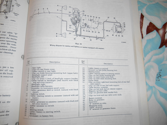
1. It's a '49 model M with 6 volt system and magneto ignition. (runs good, starts easy)
2. It has what appears to be an original factory delco-remy cutout relay.
3. It has a new wiring harness, and is wired as per wiring schematic #4, all doubled checked.
4. It has an aftermarket reproduction 4 position switch.
5. It has a new ammeter that worked real good before when tractor had distributor ignition with the same cutout..
6. Everything doubled checked for good grounding, but still no lights.
7. It also has a new single prong ignition switch going to the mag.

That about covers it. I'm going back out to the shop and take a good look at the generator brushes and see what they look like after I post this.

TIA and best regards.
Patrick
'49M
 
(reply to post at 14:41:06 11/21/13) [/quot

I checked my generator and the brushes seemed to be in good shape. Spring tension seemed OK. The middle brush is spaced at 7 commutator bars from the right brush. (clockwise) That's the setup when it had dist. ignition. Does that sound about right right? Now that it has magneto ignition will I have to move the middle brush in closer, and if so, how many bars? The service manual says no more than 3.2 bars for six volt. This is all new to me, and it excites me to be learning new stuff. This excitement is offsetting my depression over my lighting problems. lol

TIA, and best regards
Patrick
'49M
 
If you have no lights at all, then it is time to start eliminating the issues. Take a test light & install a six volt bulb. Make sure the battery is hooked up positive terminal on the battery to "ground" on the tractor frame. Take your test light and with the light switch off, check to see which side of the switch the power is on, ( which terminal lights up the test light) mark that terminal. Turn the light switch on and make sure you have power coming out of the switch to both wires for the lights. If not then disconnect one wire, and check that terminal on the switch for that wire on the back of the switch, if the terminal lights up the test light, you have power coming out of the switch but there is a short in that wiring circuit between the switch & the light(s) this wire goes to. Test each separately. When you get that far respond with your findings as this will get very lengthy to cover any and all possibilities.
 
Any way you can post a pic of this cutout? You should a regulator on that tractor, and a 3 position switch, but as Mr Slater pointed out, it could have the cutout.

As far as your lights go, Is the new switch wired the same as the old one, and is it the same style, and is the switch grounded good?

It sounds to me like you have something wired wrong in the box. Im not an expert on gennys by any means, in fact I don't like them or have any on any of my tractors, and you type of problems are why I don't!
 
The mag has nothing to do with the charging. They are 2 separate systems. A mag makes its own spark , not depending on the generator. If you got no spark when you tried to polarize the generator, find out why.
 
from what i gather you have no lights,... so why are you worried about the generator? have a good battery , switch and wire connections and ground and you will have lights.
 
(quoted from post at 17:30:37 11/21/13) If you have no lights at all, then it is time to start eliminating the issues. Take a test light & install a six volt bulb. Make sure the battery is hooked up positive terminal on the battery to "ground" on the tractor frame. Take your test light and with the light switch off, check to see which side of the switch the power is on, ( which terminal lights up the test light) mark that terminal. Turn the light switch on and make sure you have power coming out of the switch to both wires for the lights. If not then disconnect one wire, and check that terminal on the switch for that wire on the back of the switch, if the terminal lights up the test light, you have power coming out of the switch but there is a short in that wiring circuit between the switch & the light(s) this wire goes to. Test each separately. When you get that far respond with your findings as this will get very lengthy to cover any and all possibilities.

Hi rhtx55. This is all new to me, so I've never been down this road before, and I'm having a little trouble comprehending all that you have said. Please excuse this dumb A's ignorance.

When you say test light, is that something that I have to make up myself, or can I buy one at the auto parts store? I just don't have a clue. If I do have to make up a test light, I have a good 6 volt bulb attached to an old headlight reflector with one lead wire. Could I attach another lead wire to the reflector and use that for a ground wire?

When you said "take your test light and with light switch off, check to see which side of the switch the power is on." What switch are you referring too? Is it the 4 position switch, or is it some kind of toggle switch hooked up to the test light? I have to get all this straight in my head before I go any further.

What part of Texas you live at? Maybe I can drop by sometime and we can talk tractors. People interested in farmalls are as scarce as hen's teeth down here in the Victoria area. All that's down here is mostly green.

Thanks and best regards.
Patrick
'49M
 
(quoted from post at 17:48:31 11/21/13) Any way you can post a pic of this cutout? You should a regulator on that tractor, and a 3 position switch, but as Mr Slater pointed out, it could have the cutout.

As far as your lights go, Is the new switch wired the same as the old one, and is it the same style, and is the switch grounded good?

It sounds to me like you have something wired wrong in the box. Im not an expert on gennys by any means, in fact I don't like them or have any on any of my tractors, and you type of problems are why I don't!

Hello John M. When I first took delivery of my M it had an aftermarket 3 position switch and the cutout presently on the tractor. The guy had to use the battery off his chevy silverado to get it started. Once started, he unhooked the battery and the motor kept running Once unloaded from the trailer and still running, he showed me that it indeed had lights that worked.

The wiring on it was a total nightmare. Just how it ran, I'm not sure, but it ran. I tore out all the old wiring and made up a temporary harness with a new aftermarket reproduction 4 position switch that I got from Brillman. After that, the tractor ran just fine with good lights. Then one day, no more lights. And that's the way it's been ever since.

Now that you mention it, I went back and checked the wiring diagrams. Diagram #2 shows a VR paired up with a 3 position switch. Diagrams #3 &4 show a cutout paired up with a 4 position switch.

So the tractor at first had a 3 position switch pared up with the cutout. Could that maybe be what's causing me these problems now?

Here's the picture you asked for. The cutout has this number stamped on it at the base---11166766 A.


Thanks John and best regards
Patrick
'49M
 
The test light is best purchased as those are handy and not clumsy. It looks like an Ice pic with a clear handle and a black wire coming out of the butt. The wire has an alligator clip to ground it.

One of the issues that may be the problem is a broken amp gauge. I say this because if it is internally disconnected it will pass no voltage. This will also provide all the symptoms described.

Follow these directions with every thing connected and the electrical box open, and the tractor off:
With a test light, hook the alligator to the grounded battery cable at the battery. Put the test light pic probe on the other terminal of the battery. It will light because the tractor starts, and the battery must be connected and charged enough. (this gets you used to the process)
Now move the probe (leaving the ground alligator as is)to the starter switch big terminal that comes from the battery. It should also light!
Next put the probe on the little ring terminal that feeds the amp gauge at that same starter switch post. It should light!
Now Follow that wire into the electrical box. It must connect to the amp meter. Test the amp meter terminal and make sure it lights the tester.
Now put the probe on the other amp gauge terminal.
Again it must light! (if the test light does not light up at any of these test points the circuit is broken between the tested location and the battery. If the first amp gauge terminal did light and the second amp gauge post didn't light the tester, the amp gauge is bad. Replace it before any more tests. If it did light, the next test point is at the wire connecting the amp gauge second terminal with the fuse. If it has a black plastic fuse holder accessible from the front of the switch box, the fuse must be good, and the wire connecting the fuse to the light switch must light the tester both at the fuse where it connects to the side of the fuse holder, and at the light switch. (if your system has only a fuse on the 4 position switch, that fuse must be good. Put the probe on one side then the other to make sure there is power to the light switch. Next turn the light switch full Clockwise.
Test at the screw that connects to the head lights. Must have power, Next turn the switch to D position (one click from Full Clockwise) the same screw should now have power, but the probe should be dimmer.
If power to that point, put the probe on the screw going to the rear light. it should have full power at both D an B switch positions.
If power, use the probe on the screws at the light housings. If power, the bulb/s are bad, or the bulbs are not making good connection in their sockets, or it has bad ground to each lamp housing. Touch the probe to the lamp housing next to the screw (through the paint to metal) if it lights dimly, the housing is not grounded properly to the light bar, or the light bar is not grounded to the steering pedestal.

The generator wiring is next. With the alligator still connected to the battery ground terminal, Probe the wire leaving the amp gauge second terminal going to the device you are calling a cutout, to make sure the terminal is connected to the wire (It is a #10 wire bigger than the light wiring. Next put the probe on the Bat terminal on the "cutout" this will light if the wiring is good. If no light, the wire is bad between the amp gauge and the Bat terminal on the "cutout".
Now (because there is voltage at the Bat terminal, is the time to polarize the Gen. as described earlier.
It should spark. If it does not the generator may not be grounded to the engine, paint or rust could be insulating it from the engine.
Do these tests and assure us there is voltage as described above. or let us know where things go astray and we will help again. Jim
 
THat is a cutout relay. I do not believe it is wired correctly as shown. There should only be one wire connected to the Arm terminal on the Gen. It should be connecting the Gen (or Arm terminal they are sometimes called either name) on that cutout only. The Bat terminal on the cutout should be connected to the amp meter as described in my other contribution to this fix. The other wire that is connected to the F terminal on the gen should be thrown away. It is definitely not used at all for this setup. The F terminal on the Cutout is only used if there are no lights mounted on the tractor, and then the gen only charges the battery at low charge due to a grounding resistor in the base of the Cutout. Disconnect it.
The Gen's F terminal is connected to the light switch.
(and that only) the wire goes to the charge rate part of the switch, and is either grounded to the switch body directly, or grounded through a resistor that gives it low charge. In H - high charge, D dim lights, and B bright lights positions it is on high charge, grounding the F terminal with no resistor. The two switch components in the light switch are totally separate, though on one shaft. The lights are a power circuit, the Gen control is a grounding circuit. If the Cutout is connected to the F terminal and the Switch is connected, there will be no proper control with the light switch.
Jim
 

Wow Jim, thanks alot. That's a lot of good info you have there. I'll be looking for a test light tomorrow. We have Advance Auto, O'Rielly, and Auto Advantage stores here. Maybe one of those will have what I'm looking for. Will the test lights offered be dedicated to 6 or 12 volts, or will they be universal?

Best regards
Patrick
'49M
 
Assuming youre using Bob Ms diagrams, then #4 is the one you need. I agree with Jim, that's not wired right, per Bobs diagrams. The 3 position switch will not work with a cutout, its just a light switch with no connection, other than power, to the genny/regulator.You need to check all of your connections again, or possibly the cutout has been damaged. By now, if it were mine, it would have had an alternator on it!
 
Patrick does this mean you have 2 M tractors now? This should work for the 49 model.
a136064.jpg
 

Hi Dave. I only have the 49 model. You may have me mixed up with someone else. I've seen that image before in one of my manuals. I'll look it up.

Thanks buddy and best regards
Patrick
'49M
 
(quoted from post at 04:25:22 11/22/13) Assuming youre using Bob Ms diagrams, then #4 is the one you need. I agree with Jim, that's not wired right, per Bobs diagrams. The 3 position switch will not work with a cutout, its just a light switch with no connection, other than power, to the genny/regulator.You need to check all of your connections again, or possibly the cutout has been damaged. By now, if it were mine, it would have had an alternator on it!

Hi John, the #4 is what I have been using. The alternator conversions are nice and very practical. The only reason I'm hanging on to the old stuff is because of it's nostalgic value. The early M's are more nostagic than the later M's and have more charactor IMHO. That's the way I'm tuned and, why I'm taking this beating. Call me hard headed I guess. lol

Thanks and best regards
Patrick
'49M
 
(quoted from post at 14:42:48 11/22/13) They are 12v but work OK on 6 just a little dimmer. Jim

Hi Jim, I found one of those test lights at Harbor Freight today for less than 5 bucks. We'll see what it does tomorrow.

Thanks and best regards
Patrick
'49M
 
Sorry for the late response, been working way too much lately.

These Farmalls are pretty simple to work on, but it does take a bit of help from time to time. You have received some very good advice above, so I don't think the issue is very serious.
It's just hard to put into words the entire process of trouble shooting, and without being there to see for yourself, the possibilities are limitless as to what is causing the problem.
More than likely it is something so simple, it's easy to overlook.

Just guessing, it sounds to me like the fuse has blown in the dash ( next to the light switch) With all the "testing" you have been doing it is possible.
One quick hot wire short to frame connection even for a second will sometimes blow them quickly.

Yes, we can talk tractors til the cows come home.
Email is open RHTX two five at gmail dot com.
 
(quoted from post at 11:17:29 11/23/13)

Just guessing, it sounds to me like the fuse has blown in the dash ( next to the light switch) With all the "testing" you have been doing it is possible.
One quick hot wire short to frame connection even for a second will sometimes blow them quickly.

Yes, we can talk tractors til the cows come home.
Email is open RHTX two five at gmail dot com.

Thanks rhtx. I probed both ends of the fuse in it's holder, and there's power at both ends. My next post directed at Janicholson explains it in more detail.

Best regards
Patrick
'49M
 
Hello Janicholson, this is the results of your suggestions using the test light.
All points probed made the test light shine. There was no difference in the intensity of the testlight when switching from H to L at the switch. So I guess the ammeter is good, as it was working OK be fore this changeover.

No sparks though, when polarizing the genny. Touched the BAT terminal at the cutout to the field terminal of the genny. Is that correct?

I did grind to bare metal the mating surfaces of the genny and it's mounting bracket. I also probed the the generator body itself and the test light lit up. So it looks like to me that the generator is indeed grounded, RIGHT? Bad generator? The middle brush and the right brush are spaced at 7 cummutator bars apart. Does that sound normal?

The fact that the light intensity of the probe remains the same when switching from bright to dim maybe hints that there might be a problem with the 4 pos. switch. I'm just guessing there. So after doing these tests, those are the only 2 flaws that I see. Whats your thoughts?

TIA and best regards
Patrick
'49M
 
If the alligator was clipped to the grounded battery terminal, and the light came on when you touched the generator housing. the generator is not grounded. That test would indicate that the generator and ground were not connected. If the battery ground cable is attached to the starter motor, and the motor was not grounded to the engine, the starter would work correctly, but nothing else, no lights and no charge, and no spark to the polarizing.
Use a jumper cable and jump from the battery ground terminal to a frame shiny place, then test things again. Starter motors have had bad grounds to the engine. Let us know. Jim
 

Another 'wow' Jim, read on.

A big, and I mean big OOPPS!!! My bad! I had the clip of the test light hooked up to the wrong side of the battery. So everything I tested earlier is a total error.

I'll recheck everything again tomorrow and let you know the outcome. Right now I have to somehow hide these jacka$$ ears I've just sprouted, if you know what I mean.

Thanks Jim. Sorry for all the confusion.

Best regards
Patrick
'49M
 
I now have the probe clipped to the battery ground post, and probe is not lighting up at the starter switch, where the feed to the ammeter hooks up.

Does that mean that the starter switch has to have a good grounds too? Also, does the rear tank support that the switch mounts to has to have a good ground too? If all this is so, then here probably lies a big part of the problems I've been having, RIGHT? Paint on the mating surfaces of these parts is the problem, RIGHT?

Oh, BTW, the genny now does not light up the probe. So I guess I have good ground with the genny now.

TIA and best regards
Patrick
'49M
 
Now we are getting to the problem.
The light is detecting voltage availability.
From the grounded terminal post of the battery (round post, not the clamp), to the other terminal post on the battery, the battery voltage is lighting the tester. If you now clamp the allegator jaw on the terminal clamp instead of touching the post, it is measuring the battery voltage, and the conductivity of the clamp to post.
Assuming the battery terminals are clean and conductive. Clamping the alligator to the grounded terminal, testing now eveluates the conductivity of the connections proceeding from the non grounded terminal to the far end of the non-ground battery heavy cable. Touch only the metal of the bat cable terminal end, not just the threaded switch post. Next touch the threaded post and nut. If light go on. Then touch the ring terminal on the wire going to the amp meter. if no light, remove and clean the terminals with 200 grit (or so) silicon carbide paper. Then reassemble and spray clear spray laquer on the clean fittings.
If there is voltage at the ring, push the probe into the wire going to the amp meter (through the insulation. If no light, the connection to the terminal is corroded possibly inside the insulation. If good and light is lit, go to the amp meter and check the ring terminal at the amp meter input. If no light replace the wire from the starter switch. Continue this action as described in the former post until you find the bad connection. Jim
 

Jim, does the starter switch body and gas tank rear mount have to have a good ground to the tractor chassis? Right now they don't due to new paint. I'd like to take care of that if necessary before I do any further testing.

Thanks Jim and best regards
Patrick
'49M
 
There are several differing starter switches. Some mounted on the tank mount, some on the light switch, some on the Starter motor (IIRC).
None of the switch bodys need to be grounded. The steering wheel support post, and the electrical box need to be grounded to assure light ground path. Jim
 
Could it be that the wire to the ammeter is on the wrong side of the starter switch. If it is it probably only has power when the switch is activated.
I am assuming you have the stock switch with the large push button.
Dennis
 
Good point.
I made an assumption of original wiring and following a diagram. That wiring mistake would an answer if correct. Jim
 

Jim, this is how my starter switch mounts. The non grounding cable (-) of the battery connects to one of it's lugs. The other lug receives the cable going to the starter motor, and the lead wire going to the ammeter. Is this correct?


Now, I clipped the test light end to the grounding side (+) of the battery, then touched the opposite side (-) of the battery and the light shined.

Next, with the testlight still clipped to the grounding side, I touched both ends of the cable that goes from the starter motor to the starter switch lug, and no light at either end. It didn't mater whether I touched the metal ends of the cable, threaded post, or nut.

Next i touched the ring end of the lead wire going to the ammeter, and no light again. Did I do all this correctly? All the mating points are clean.

TIA and best regards
Patrick
 
You found the problem. The lead going to the amp meter goes on the lug with the battery cable, not the one going to the starter. Simple fix. Easy mistake to make. Jim
 
(quoted from post at 19:04:25 11/24/13) You found the problem. The lead going to the amp meter goes on the lug with the battery cable, not the one going to the starter. Simple fix. Easy mistake to make. Jim

AH MAN! DOUBLE "WOW"!!! I GOT LIGHTS!!! And I'm shouting it from the rooftops lol. The 4 position switch works great, and does what its suppose to do. I got both bright and dim lights, and the tail light stays bright ether way.

The ammeter needle goes over to the left (-) at about -10 on bright, and about -9 with dim lights. All this with the motor stopped. I'll started it up tomorrow and see what happens.

You are DA MAN JIM! Thank you, thank you, thank you! As you can see, happy days are here again. I'm going to have a drink or 2, or 3 on that one. Now I can relax, and not have to tear my hair out anymore. lol

That was a lot of BS just because of one misdirected wire. Oh well, live and learn.

Best regards
Patrick
'49M
 
You are very welcome. Dennis also guessed the issue due to the evidence. You cannot say you are not experienced with Farmall wiring. Jim
 

We sell tractor parts! We have the parts you need to repair your tractor - the right parts. Our low prices and years of research make us your best choice when you need parts. Shop Online Today.

Back
Top