Engine won't STOP running

equeen

Member
Finally connected alternator to the electrical circuit on my Super A. No ballast resistor since using 12v coil.

She fires up fine with ignition switch on, charges at about 14.2; then keeps running after pushing the ignition switch off. I disconnected wire from coil to distr to get her to shut down.

She won't start with switch OFF.

I have NOT yet added an idiot light or 15 ohm resistor to the circuit.

She starts and stops fine with the wire disconnected from spade 1 on alternator. But she doesn't charge.

Your comments???? Thanks.
 
Comments? I have several.

The first is I probably should keep quiet and not make the rest of my comments.

The second is that if you don't understand how an alternator charging system works, you shouldn't take on a conversion.

The third is that if you ignore the previous comment and decide to do it anyway, you should completely follow the instructions that have been given frequently on this site.

The forth is that the answer to your problem is in your own post.
 
Thanks, especially for "the forth". I suspected as much but wanted to make a fool of myself before "completing" the job.
 
Yeah, they be tough! And, sometimes one or more makes assumptions - false assumptions.

This was not a 12v conversion - simply an attempt to wire up an existing alternator that had mangled and jangled wiring, cut wires, etc.

But, I did use a wiring schematic for a "conversion" and should have put the idiot light and diode in the circuit - even though I had no clue as to why - other than someone said do it.

Yep, they can be tough - and I give them an opportunity on occasion to get out their whips. But, hey, my skin is thick. Appreciate their help.
 
Though not your conversion, it was someone's as there were no alternators on A Farmalls At any rate the light/resistor/or diode will make it dandy. Jim
 
What do you mean harsh he told him what he was doing wrong. Its awful to see what some people do to an old tractor. Like removing the fan and shroud to put an Alt on a Cub then putting an electric fan on. You should have seen the wiring. Why install 12v on a Cub is silly when the old system will work just fine.
 
Harsh? Don't know, but I had to use Preparation H last night on a raw hiney - no not tractor hiney.

I still want to know why..... Nothing real elaborate just the basics........

Why will an idiot light allow the engine to shut down?

Or, why will a resistor alone do it?

Why doesn't the ignition switch do it as it does with a generator unit?

And why do I want to know why? Just because.

Furthermore, I want to know why folks still say that the sun comes up and the sun goes down when we learned from folks over 500 years ago that the earth is not flat and the sun does not revolve around the earth - thus does not come up or go down.

Y'all have a great day. I shall!
 
Queen, to hopefully add some understanding to the posts you received below, here are my inputs:

A small incandescent "Idiot Light" (basically a resistor that happens to also light up) orrrrrrrrr a 15 Ohm Resistor orrrrrrrrrrrr a diode will work to prevent the voltage thats present on the alternators small (1R) spade connector from backfeeding voltage to the coil which allows the tractor to run even if the IGN switch is off.

The reason for applying that voltage to the alternators small 1R terminal in the first place is to provide it with excitation voltage so the alternator begins to charge prior to it becoming self exciting. The problem is once voltage is present on that terminal when you shut the IGN off that voltage can power up the coil even with IGN off so she keeps running. To prevent that a current limiting voltage dropping resistor or idiot light in the circuit or a diode reduces or stops that voltage from backfeeding the coil yet still allows sufficient voltage and current to initially excite the alternator.

So placing the device in the 1R feed circuit (from coil or ign switch) to the alternator for initial excitation will stop the run on problem.

Got it???

best wishes n God Bless

John T
 
u have to have electric to an alternator,( to excite it) before it will charge. once the process has began, it will continue; it will continue even after ignition switch is cut off, as long as engine is turning. u have to disconnect alternator circuit from engine to stop the process; if not alternator will continue to supply current to engine.
 
Equeen - You shoulda got a little more sympathy here. I added 12-volt alternator to my "H", added a diode from charlieu, [works great], and have took apart the ammeter box and blew out all the dead bugs. The old "H" really runs. However I have not the foggiest idea how or why the alternator works. Best I can figure, it is magic and witchcraft.
 
Ah, so.........

Hmmmm? So, power from the battery to ammeter to post (a or whatever) on ignition switch goes to post (b or whatever) on ignition switch when it is pulled on, then down wire to coil and other wire to generator to exicte her on spade terminal 1.

The #10 wire from the alternator provides the charge through the system to the battery.

The #1 spade terminal gets its hots from the battery (at least initially) to excite that unexcited alternator and get her to charge.

And, since the wire from #1 spade is connected to the same post on the ignition switch as is the wire to the coil - the alternator keeps current flowing to the coil as long as the alternator is spinning.

So, by magic, a resistor allows current to flow only one way???? It allows the needed current/ excitement to get the generator to charge, but prevents her from backfeeding to the coil.

Do I get it now?
 
(quoted from post at 05:40:53 06/02/13) ...Best I can figure, it is magic and witchcraft.

Most electricity is. If it wasn't magic wouldn't you be able to see it!?!

So if you put the light in the circuit (acting as a resistor) will it be on the whole time the tractor is running?
 
When the ignition is first turned on at start up, the ignition switch supplies "exciting signal" voltage to the electronics of the internal regulator through Terminal1 (or L on a Hitachi). The regulator sees this voltage as a reason to start charging. When the alt spins up, the charging voltage (internal) is switched to that terminal by the electronics of the regulator, and stays on that terminal as long as it is charging. When the ignition is shut off that internally supplied voltage is still being supplied from the regulator, and with no diode/light/resistor, it supplies the ignition coil with voltage to run the tractor.
When first turned on the voltage (using a light bulb example) the voltage goes through the light bulb filament and to what is now an apparently grounded terminal. The bulb is lit.
When running and charging, the regulator puts 14.2 volts on the formerly grounded side of the filament, thus with both sides at 14.2v the filament is cold light off. When shut off, and coasting down, the ignition side of the filament goes to 0volts but the coil appears to be a usable path for the charging 14.2. the filament has a high enough resistance that even though it finds a "ground" through the coil, it limits the current (by glowing) as the alternator winds down, passing voltage and becoming lit, but insufficient current to run the ignition system.
thus no spark.
When below the speed at which it will supply charging voltage (maybe 500RPM at the alt shaft) the regulator cuts the supply voltage to the #1 terminal and resets it as an apparent ground.
Turn on the key, light on
Start engine---charging, light off
Shut off engine light on as it coasts down then light off.
Alternator failure (some of them) light on because it goes back to no charge state and the light is grounded as though the alt was not turning.
I hope this helps. Jim
 
Excellent, Jim! Excellent. It helps with understanding. Tractor may not run any better than if I had just followed the "rules". But, knowing the "why" is far more interesting.

Glad that I and others kept the questions going. More pleased that you folks with answers, gave us the answers. Whips or no whips, y'all do good work with the forum.
 
I was thinking about connecting it to the valve stem in the left rear tire, but couldn't figure out how to keep the wire from wrapping around the final drive. Think I'll just stick the ignition switch end of the naked wire into the radiator fill neck instead.

Now, about the sun "coming up" or "going down"??
 
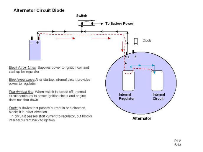
Maybe a picture will help.

Diode allows current to flow one direction but not the other.

Resistor and light limit the current. Ignition system takes about 4 amps to run, alternator only takes a fraction of an amp to start up. When shut off the resistor or light limit the current to a level less than that required for ignition circuit so engine dies.
a117454.jpg
 
Not quite but youre gettin there.........Unlike a Diode, a resistor or idiot light does not stop current flow in one particular direction, but it drops sufficient voltage and limits current to enough of an extent that run on is prevented if its in the excitation circuit.

Now ya got it?????

Fun chat, glad were able to help you understand all this

Best wishes n God Bless

John T
 
Okay, used a 15 ohm 1/2 watt resistor from RadioShack. Didn't pay any attention as to which end went where (based upon a comment by someone on the forum a year or so ago).

Tractor fires up great, charges great and shuts down.

Interesting that I have to bring the gas down to idle and it takes her 10 seconds or so to totally die after ignition switch is off. (She doesn't die if I leave ignition on and take gas back to idle - so resistor is what is shutting her down).

Works well enough to suit me - but is this "slow" shut down normal?


BTW: For teddy - First I ran the wire to the oil pressure gauge as you suggested and now I have oil all over the place, my dog scratched me, my cat bit me and my wife ran off with a vacuum cleaner saleswoman. Thanks a lot for your sorry advice.

Gene
 
"but is this "slow" shut down normal"

The ones Ive used a resistor on seemed to shut down right away, the RPM and Alternator and its internal regulator all make a difference. Of course, if the resistor (or light) is of higher ohms resistance that affects it provided its not so high theres insufficient excitation to get the alternator up n charging at relatively low RPM's

You have the picture now, fun chattin with ya

John T
 
Well this is how the alternator works in simple terms. You have the big stud on it which is the charge output. The #2 wire tells the V.R. when to slow down or shut down the alternator. Then the #1 wire is the excite wire and once excited that wire stays hot with or with out the ignition switch on till the alternator stops spinning so your problem is that the alternator is back feeding the ignition so you have no shut down. Install an Radio shack 276-1661 diode in the #1 wire line towards that alternator and your problem will be fixed
 
I say it's your tractor and as long as you are not endangering yourself or someone else do wah it best for you. My usual avocation is X-ray equipment field engineer and I have been an electronic engineering technician for 30 years. The resistor and light will work but allows some minimal current when you shut the ignition switch off. A diode is an electronic switch that will only pass current in one direction. When I converted my SC case to twelve volts I used the diode. It ran eight years burning oil until I sold it. :)
 
(quoted from post at 07:44:36 06/02/13) I was thinking about connecting it to the valve stem in the left rear tire, but couldn't figure out how to keep the wire from wrapping around the final drive. Think I'll just stick the ignition switch end of the naked wire into the radiator fill neck instead.

Now, about the sun "coming up" or "going down"??

You would need slip rings like an AC generator.
 
Gene:
Teddy's advice is useful, but needs clarification: there are available some on/off switches that are controlled by oil pressure. They function the opposite of an oil pressure warning light switch, so they can be used to power a device that you only want to work with the engine running. Some examples in automotive would be an electric radiator fan, an electric choke, an electric fuel pump, and an alternator on a diesel car. There are times where the oil pressure-controlled excite circuit is necessary, but for battery ignition it generally can be ignored.

karl f
 
I always use a diode I think it works the best. From now on I will use the wiring harness Todd Young is showing us. Thats the sweetest thing I have seen & it is way to cheap.
 
Maybe a description of what happens in the alternator will help clarify why a resistor or diode is needed in the #1 terminal. Here is a link to the service manual for that series alternators.

http://www.autoelectricservice.net/images/Delco_10SI_Technical.pdf

If you follow the wiring diagram for the regulator you will see that the #1 terminal is connected directly to one of the brushes to provide electrical power to the rotor to create the magnetic field necessary for the alternator to operate. The regulator controls the connection of the other brush to ground to control the voltage. You can also see that the diode trio inside the alternator provides power internally once the alternator starts to charge.

This internal connection is also why there should be some sort of current limitation on the circuit for the #1 terminal. Without some sort of current limitation the entire output of the alternator will be available at the terminal if the connection between the output stud and the battery should become an open circuit.
 
The gen light, or resistor, will allow only about 1/4 amp to backfeed from the alternator to the ignition coil, not nearly enough to power the coil and make a spark, so the engine shuts down normally.
A diode totally blocks any backfeed from alternator to coil, but will allow about 2-3 amps to flow from the ignition switch to the alternator, nearly doubling the load on the ignition switch and wiring. This can cause voltage drop and weaker spark from the coil.

Thats why I perfer to use the gen light. 1 it only adds 1/4 amp load to the ignition circuit, so the coil sees less voltage drop and makes stronger spark, 2 it serves as a charge / no charge indicator, 3 It reminds you that you forgot to turn off the ignition, so you do not run down the battery.
 
Thanks very much for your post.

I've been thinking - sometimes dangerous for me.

Is the light idea similar to, or identical to, the idiot light on modern autos? That is, the light will come on momentarily at times, but then goes out and stays out during normal operating/driving conditions? When the light comes on during normal conditions, it's a sign that there is a problem?


So, the light serves two purposes. It allows for a normal shut-down of the engine AND it provides a visual sign when there is a charging problem?

Gene
 
Yup, does exactly what the alternator idiot light on the car does... Best thing to use for an idiot light is a panel mount LED. I got mine at the auto parts store.

When you came on here and proclaimed that you knew what you were supposed to do, purposely didn't do it, and then were surprised at the negative result... That's pretty much the pet peeve of any farmer, so you gotta expect some harshness...
 
Thanks for the idiot light info.

I accept whatever harshness is meted out - and sometimes have a little "fun" with it.
 
continued from post below, I suppose..

And sometimes we learn MORE by not following all instructions initially - and advising what we have not done.
 
The light coming one with the engine does show that there is a problem with the charging system but there can be other problems where the light will be off and the alternator still not work.

Normally there will be a resistor inside the alternator between the #1 terminal and the alternator case if the alternator is designed to be used with a light. Since the resistor is not used if the alternator is used with an ammeter it is quite possible to see them used in applications with a light. The alternator will work okay with the exception that the light will not be as bright with the switch on and the engine not running. In this situation if the field circuit from the #1 terminal though the bush, the rotor winding, the second brush and back to the regulator should become open the alternator will stop charging but the light will not come on. In this case the light will now longer come on with the switch on and engine not running.

If the diode trio fails with open diodes it is possible for the alternator to continue to charge even though the light will be on. The alternator output will be somewhat limited due to the voltage drop through the indicator lamp. If a tractor is wired with a diode rather than a light it is quite possible to have this type of diode trio failure and never notice a problem since the field coil will continue to be powered through the external diode. This problem was mentioned in an earlier post where the #1 circuit will have several amps flowing through it with no indication of an alternator problem
 
I use a diode, I get them from JD, think they came on a pull type forage harvester. My parts guys know what they come from when as for one.
 
An LED must be shunted with a 12ohm resistor to light. It will not pass enough current to excite the regulator. Jim
 

We sell tractor parts! We have the parts you need to repair your tractor - the right parts. Our low prices and years of research make us your best choice when you need parts. Shop Online Today.

Back
Top