Farmall 1456 wiring question

Our Phone System is Down!

Please use the Contact us Form

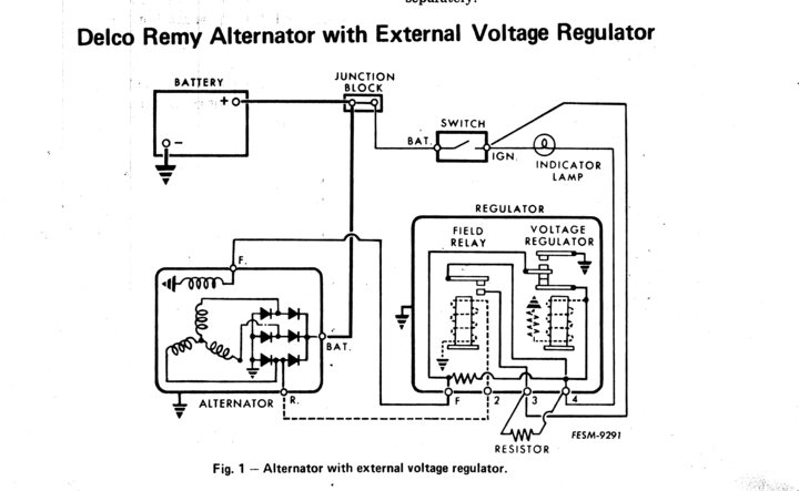
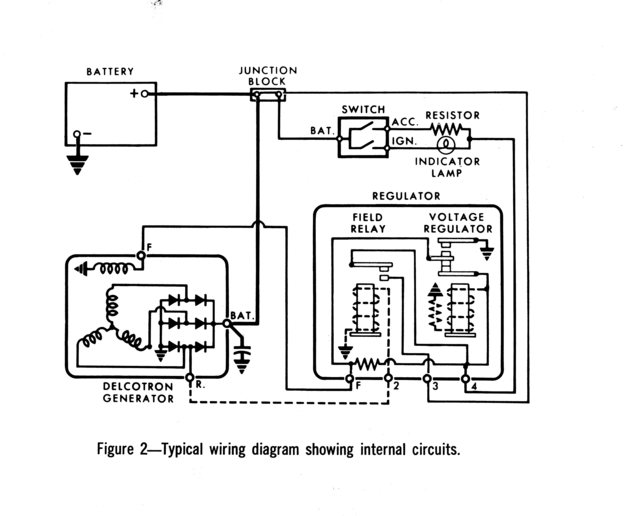
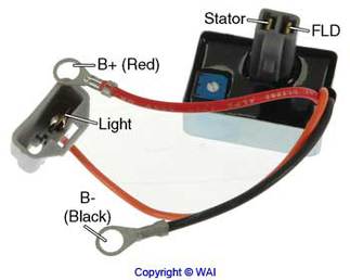
Ok here goes. Im a JD guy but my brother just bought a Farmall 1456. It"s in pretty good shape very straight but needs a little TLC. I am in the process of helping him rewire it. I have ordered wiring harnesses and begun tracing wires, so are not connected and most are cracked and frayed. Before we started the alternator was not charging at all. It is an internally regulated alternator because the voltage regulator has been removed. My question is what do I do with the wires that go to the voltage regulator and resistor? Currently they just had them unplugged and hanging there. If it doesn"t charge after new wiring I will be getting a new alternator but I want to do the wiring right and need to know if they need removed or spliced or whatever. Thanks for any help you can give
 
I rebuilt an 856 last winter including complete new wiring harness and I replaced the external regulator Delco 10DN alternator with an internal regulator Delco 10SI.

To adapt the internal regulator alternator to work with the IH charge light and stock wiring harness, Down under the dash, where the external regulator plug is mounted, fabricate a jumper wire to connect the outermost terminals at each end of the regulator plug. All that takes is about 4-5 inches of 14 ga wire and two flat blade male crimp on terminals.

The alternator charge light will now ground to one of the two wires in the little square alt plug up at the original alternator mount.
Buy an auto parts regulator repair plug for an internal regulated Delco alternator (10SI).

Put an eylet terminal large enough to fit on the big "BAT" stud on the alternator rear, on the #2 alternator repair plug wire (usually a heavy red wire).

Add a male spade terminal terminal to the #1 wire(usually a small white wire) on the alternator repair plug at the alternator.
Plug this male spade terminal into the correct. terminal in the original alternator plug in the new wiring harness.

It's been long enough that I don't remember which of the two terminal in the new wiring harness needs to have the white #1 alt wire plugged in, but it will make the alt light come on when the ignition switch is on when you get the right one.

Tape up the harness where the original and the new adapter plug go together, and your good to go with an internal regulated alternator with a stock working charge light, all without cutting up your new stock wiring harness .:)
 
Just to clear up my regulator plug jumper wire instructions. My jumper wire connects only the outermost terminal at each end of the original regulator plug. Nothing is plugged into any other regulator plug terminals. The resistor wires can be plugged to the resistor, even though it is now unused.
 

I wouldn't take anything for granted. I would make sure the alt. has an internal resistor and take it and have it checked. I just went through a charging problem with a 756 I had just gotten. After checking the alt. and getting a new V.R. and still no charging, I started checking wire continuity and someone had the wires reversed on the alt. Ended up being an easy fix ,but time consuming.

Good luck.
 
So a jumper wire between the two outer most plugs on the voltage regulator plug. Then the repair plug is plugged into the original plug coming from the wiring harness. One of those wires goes to the BAT stud and the other one goes to one of the two prongs where the original wiring harness plug went into the alternator. I assume all the other wiring stays the same. Just want to be sure I have it right. Thanks
 
Correct, #2 repair plug wire goes to the Bat stud along with the original bat wire.
#1 wire in the repair plug goes to one terminal in the original alt plug. The correct one will turn on the alt light when plugged in with the ign on and engine stopped+ repair plug connected to the alternator.
Jumper the outside terminals in the in dash regulator plug.

All other wiring remains stock.
 
If you want to eliminate any confusion on the wires just connect all four of the wires together at the voltage regulator and the connect both of them to the #1 terminal at the alternator.
 
"If you want to eliminate any confusion on the wires just connect all four of the wires together at the voltage regulator and the connect both of them to the #1 terminal at the alternator."


Whoa Qwen, connecting all four regulator plug wires together is bad idea of the year.
#3 regulator plug wire is direct from the battery, hot all the time.
Connecting the #3 wire to the other 3 would keep the alternator field energized all the time, killing the battery in a few hours, also would disable the alt light circuit and backfeed power to anything on the ignition circuit.

No one do this,real bad idea.
 
(quoted from post at 21:10:33 05/04/12) "If you want to eliminate any confusion on the wires just connect all four of the wires together at the voltage regulator and the connect both of them to the #1 terminal at the alternator."


Whoa Qwen, connecting all four regulator plug wires together is bad idea of the year.
#3 regulator plug wire is direct from the battery, hot all the time.
Connecting the #3 wire to the other 3 would keep the alternator field energized all the time, killing the battery in a few hours, also would disable the alt light circuit and backfeed power to anything on the ignition circuit.

No one do this,real bad idea.

Dang it!! The first school IH sent me to was on electrical systems and they must have screwed up and got it wrong!

Or maybe not.

You would be correct if Mother Harvester had gone along with the way that Delco Remy shows the 10 DN system wired, but IH must have thought they had a better idea. The difference is in how the resistor is wired into the circuit. That change also required a change in how power is supplied to the #3 wire.

Like the #4 wire, the #3 wire also comes from the ignition switch. If it were hot all the time there would be a back feed through the external resistor and charge lamp to the ignition switch which would continue to power anything else (fuel gauge, ignition coil, cab relay) connected to that side of the switch.

The diagram below shows how IH wired there machines when using a charge light and 10 DN alternator with external regulator.

c3719_lrg.jpg


This diagram shows what Delco Remy has in their service materials

c3721_lrg.jpg


I didn't say it was the best way, only that it would work. As long as he is going to replace the wiring harness the best solution is to use a custom made harness designed to with a 10 SI rather than a 10 Dn.
 
Thanks for the heads up Owen. I guess I should not absolutly trust an internet download wiring diagram , especially a 66 series diagram, and assume it is correct for a 56 series. The one I had handy(66 series diagram download), clearly shows the #3 wire connected to the battery at the starter.

This and your post had me really confused, so I headed out to the shed to stick a 12V test light in my 856 regulator socket to see if that #3 terminal is hot all the time or is switched. I found your diagram correct, #3 has switched power, so It would not discharge the battery through the 10SI field circuit when parked if all 4 regulator wires were connected together.

One question though,looking at your top diagram from IH. My jumper wire conversion only connects the F wire to the #4 gen light wire so the F wire can excite the field in the 10SI and make the factory charge light work.

Would not connecting all 4 regulator plug wires in effect connect #3 to#4 and disable the charge light, in effect wiring switched power around the gen light ??

Not trying to play know it all or start a fight, just trying to get the guy correct info to do his 10DN to 10SI conversion without cutting up a new wiring harness.
Thanks for correcting me on #3 having switched power on a 56 series IH.
 
You are correct. Wiring all four together will put battery voltage on both side of the charge indicator light and it will not light up. Besides that it is bad practice because it takes both the resistor and the light bulb out of the circuit and you lose their protection from having excess current in the excite circuit of the alternator if a problem should develop in the battery wire to the alternator.

When I posted the original comment it was in reply to not being able to get the alternator to start to charge. He also mentioned that his wiring was in bad shape and some of the wires may be broken.By connecting all the wire together there was a much better chance that he would at least get power to the alternator for the excite terminal.

The wiring for the 10SI excite circuit should have power coming both the the light bulb and through the resistor. The resistor should be there so that the alternator will start to charge even if the light bulb is bad. Your method of connecting the #4 wire to either or both of the F and #2 wires and then connecting them to the #1 terminal at the alternator and adding a jumper between the battery output terminal and the #2 on the alternator is probably the best you can hope for using the original harness.

Another unfortunate side effect of switching from a 10DN to a 10SI is the warning light will not be as bright with the newer alternator. The 10SI rotor only draws half the amps as compared to the 10DN. The higher resistance in the rotor winding will cause the light to be dimmer.

It is too bad the IH did not use the same wiring system as as shown in the Delco Remy diagram. It would then be simple matter of connecting the #4 wire to the #1 terminal on the alternator and the the #3 wire to the #2 alternator terminal.
 
So I have been reading the posts and then took a look at the alternator on the tractor and it is an externally regulated one rather than an internal which I first thought. What they had on it was a Transpo D713L regulator on it. I guess what I need to do first is figure out if this alternator works or not with my new harnesses. As it was wired B+ to alternator top post and B- to ground with the regulator plugged into the alternator. The orange wire was connected to one of the wires from the original harness. Question is should this setup work without any other wiring modifications where the original regulator used to be. As I said before the original regulator was removed and wiring was just left hanging. The alternator looks newer and I want to check it before I get a new one. I have all the old harnesses removed and the one to the alternator was laying on the turbo and two wires were burnt through.
 
The regulator you have requires only one wire to make it work. It also has provision for an additional wire to use the indicator light.

c3722.jpg


The B+ should be connected to the battery terminal on the alternator and the B- to the ground terminal. It should work without a wire on the light terminal. Like the one wire 10SI alternators it may take a high rpm to get it to start to charge. If it doesn't start to charge at high idle you can try putting battery voltage on the light terminal.

Single wire alternators depend on residual magnetism in the rotor to provide enough current to enable the field coil in the rotor to start to work. When they sit for a long time they can lose enough residual magnetism that you have actually have to polarize them to get them to start to work. Putting voltage on the light terminal will do that since it is connected to the original R terminal on the alternator.
 

We sell tractor parts! We have the parts you need to repair your tractor - the right parts. Our low prices and years of research make us your best choice when you need parts. Shop Online Today.

Back
Top