1566 hydraulics question (pic)

biggerred

Member
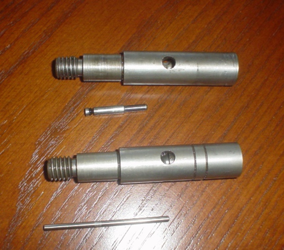
I pulled the guts out of the aux valves to replace leaky O rings and found two different types of actuator pistons. The book doesn't describe the piston in any detail, and the diagram doesn't either. Which one is right and where did the "wrong" one come from?
 
lets try again
a62071.jpg
 
The top one in the picture is from a lower pressure older tractor. BUT, the bottom one is also made in two different size rods. I can't tell from picture which one you have but the smaller rod is for higher operating pressure used on later higher pressure systems to obtain higher unlatching pressures. You will find them mixed and matched depending on who worked on tractor or who added valves. You almost have to have both the rods side by side and measure to know for sure which one you have. At any rate, you will have to find the o-rings and back up washers that fit the pin to repair valve. The top style, pin comes with o-ring on it as o-ring is so small you break a lot of them putting them on.
 
Both from the same tractor. The pins are under the plungers they came out of. There was no washers in them, or on them, just 3 detent balls, the ball and cup on the inside, and (not shown) an O ring at the base of the threads. Any problems running on the same tractor?
 
They can very well be from the same tractor, no problem and you can install either kind back in those valves. What I am saying is that the detent mechanism itself is rated for different pressure detent settings. In other words, the old 1600 psi 706 you set to trip at below that pressure and the 2500 psi 1566 was set higher so they had to change the detent to accomodate that setting. The bottom detent has the o-ring right inside on the threaded end and is held in with a driven in metal cup . By detent settings I mean you pull lever , it stays and when system reached preset pressure it trips back to neutral. Actually, I think a lot of guys are just holding the valves until they get cyl where they want because those detents were not all that great.
 
I did a lot of head scratching today as I was looking at the diagrams in the book, cause neither one of these fellas had the little cup the pic was showing. They were screwed in just like you see them (straight into the spool, through the large spring and collar)
 
The little cup, back up washer and 0-ring are right inside of the threaded portion on that lower one . If it has none, no wonder it leaks. Has to have an o-ring inside for pin to seal on. If you have a service manual it will show how you pull the cup out of actuator. And, yes, you screw in to increase unlatching pressure. Here is how I do a quick adjustment of the pressure to suit my own needs. After valve is fully assembled, engine running, lower hitch all the way, put position control lever all the way down into action control which dumps most of the oil going to aux valve , pull valve to latch, then pull position control lever to raise position and valve should unlatch. Keep turning set screw in until it will not unlatch, and then back it off again until it consistently unlatches. You are supposed to use a flow rater of course but that is another story.
 
went back and double checked where you said and, bingo-theres a cup in the end of it. I never noticed the ends are different between the two as they look so much alike in profile. Learn something new every day as they say. Thanks for your help.
 

We sell tractor parts! We have the parts you need to repair your tractor - the right parts. Our low prices and years of research make us your best choice when you need parts. Shop Online Today.

Back
Top