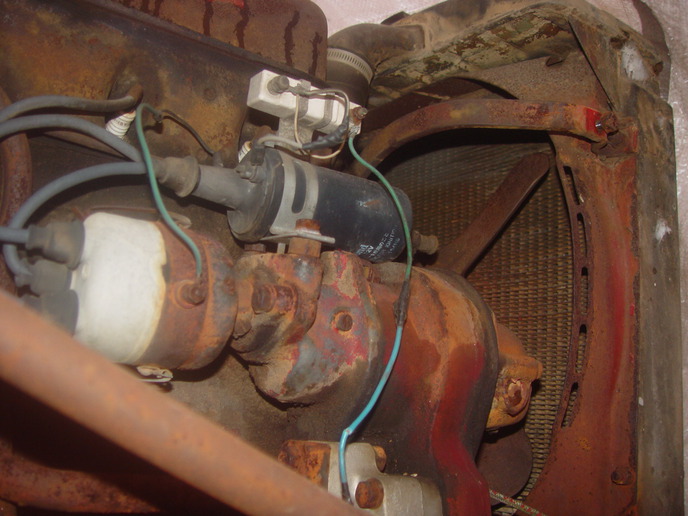
Alternator posts 1 and 2

Our Phone System is Down!

Please use the Contact us Form

We are working to resolve the issue ASAP! Thanks for your patience!

equeen

Member
Alternator (Delco Remy 1102 851 55A 6A19 VNF - whatever all that means)has 4 "posts".

Bolt "post" for grounding.
Bat post
Post #1
Post #2

Perhaps more electrical questions to follow - but wire from post #2 is connected to alternator BAT post.

To what should a wire from post #1 be connected?

What is its purpose?

Thanks.
 
(quoted from post at 23:24:37 11/04/11) Alternator (Delco Remy 1102 851 55A 6A19 VNF - whatever all that means)has 4 "posts".

Bolt "post" for grounding.
Bat post
Post #1
Post #2

Perhaps more electrical questions to follow - but wire from post #2 is connected to alternator BAT post.

To what should a wire from post #1 be connected?

What is its purpose?

Thanks.

Without knowing the application we can't say for sure where the wire should be connected.

The purpose is to provide initial voltage through the regulator to excite the fields so the alternator will begin to charge. When used with a light the terminal can also be used to indicate that the alternator is charging.
 
1 or ig is supposed to be keyed voltage from the key switch. Normally there is a resistance wire going to it or a wire with an external resistor on it. I work for a Deere dealer and the older 30-40 series tractors used the same alternator. Deere had a single wire for the resistance but they offer a kit to put normal strand wire on and plug a resistor in-line.
 
Okay, more details...
Rusty ole Farmall Super A that I'm trying to repair/get running - not restore.

Someone converted to 12v alternator system and the wiring, what's left of it, is as follows:

Negative coil to distributor
Positive coil to "resistor" (white ceramic thingy)mounted with coil bracket.
"Jumper wire from left post on "resistor" to right post on "resistor".
Wire (cut) from right post of resistor apparently went to right small post of solenoid.

Alternator:
Ground post wired to ground
Post 1 wire cut
Post 2 jumpered to "bat" post.
Bat post wire of alternator to Ammeter
Jumper wire from same side of ammeter to fuse?
Wire from other side of ammeter to battery cable post of solenoid.
 
My previous post suggested that a wire may go from the ballast resistor to the solenoid. I'm having doubts about that.

Does the wire from the right side of the resistor go to the ignition switch?

Does wire from alternator post "1" go thru some type of warning light then on to the switch on the same post as the resistor wire per above?

Photo of coil and resistor, and cut wire.
a53003.jpg
 
Im no alternator expert but if its similar to the Delco 10 SI family of internally regulated alternators heres what No 1 and No 2 terminals are for:

Of course, frame ground the case with the big main output stud wiring to the ammeter/battery:

SMALL SPADE TERMINALS 1 & 2

#1 Thats the external connection used to excite the alternator until such time (and RPM) that it becomes self excited....

That needs to be wired to a voltage source that becomes hot when the ignition switch is switched ON. So, where are such sources.

a) Well the IGN output of the ignition switch is a good source,,,,,,,,,,,

b) The same point electrically is where the wire down from the IGN switch wires to the high input (NOT to distributor) terminal on the ignition coil on non ballast resistor systems,,,,,,,,,,,

c) The same point electrically is where the wire down from the IGN switch wires to the high input (NOT to coil) side of a ballast resistor on ballasted systems

Soooooooo take your pick and wire the small No 1 terminal to any of the three locations listed above.

HOWEVER: It may happen that the tractor will still run after you turn off the ignition (alternator backfeeds coil) Sooooooooooo you fix that by installing a 10 ohm current limiting resistor in the wire from the source to the alternators No 1 terminal

ORRRRRRRRRRRRR some install a 3 to 5 amp 50 PIV or more diode in the line from the source to No 1 on the alternator (wire cathode band end towards alternator)

ORRRRRRRRRRRRR some install a small incandescent "idiot light" in that same line which prevents backfeed, limits current, and provides an indication of charging


# 2 Thats the voltage sensing terminal used to measure battery voltage so the regulation circuit can do its job. Many gents simply jump wire from No 1 up to the big main voltage output stud since thats "nearly" the same voltage as on the battery.


SUMMARY you can excite a GM 10 SI family of alternators by feeding off the input (NOT to coil) side of an external ballast resistor. However Id add a series 10 ohm resistor or a diode in that wiring to prevent backfeeding the ignition coil. Id wire the No 2 terminal to the big main output stud

IF THATS NOT THE ALTERNATOR YOU HAVE (GM 10 SI family) OR I MISSED ANYTHING HOPEFULLY THE OTHER FINE GENTS CAN ADD TO THIS

John T NOT an alternator expert
 
I see the coil is marked "12 volt"-was a 12 volt coil added at some time and the resistor "shorted out" with the white wire[instead of being removed]

After that, follow John T's description of the terminals.


Alont
 
GOOD CATCH, I cant hardly read what it says on the coil?? But if its a 12 volt coil and that white wire indeed just shorts out the ballast (that works as no ballast should be used if? its a true 12 volt coil), the only other wire that blue/green must be the feed wire down from the Ignition Switch.

If its a true 12 volt coil he needs to throw that rats nest mess and ballast all away then where the ign wire (blue/green) attaches to the coil input (NOT to distributor) terminal he needs to attach another wire and a 10 ohm resistor (or diode) then down to No 1 on the Alternator.

So simple if we were there but harder to describe in words if hes not good with electricity.....

John T
 
Thanks for all the great responses.

Before I even attempt to fire it up I shall replace all wiring - initially the wiring necessary to get it running without lights and without alternator (if it will run without alternator wired up).

So, next statement/question...

Solenoid is mounted onto gas tank mounting bracket. 4 post solenoid.

Large right post is wired to battery positive via heavy cable. Post is also wired to ammeter via small wire.

Large left post was apparently cabled to the starter switch on the starter (however the starter switch is missing and will be replaced).

No wire on small left post on solenoid.

Red wire on small right post on solenoid - and another wire is spliced into this wire. The ends of these two wires go....nowhere...they're cut.

Question: Where should a wire off the small left AND/OR small right solenoid post be attached?

(Note: I'm looking at one wiring diagram that doesn't even have a solenoid. The heavy battery cable {positive} is wired to the starter switch on the starter and a smaller wire feeds from the starter switch to the ammeter. I'd certainly like to eliminate the solenoid if it's possible/reasonable.)
 
If the Solenoid is a Ford type, of course the big main input side is where the big + battery cable attaches plus maybe a 10 or 12 gauge that goes to the ammeter. The other big output side wires to the starter.

On the small terminals one may be labeled S and the other I ??? You wont be using the little I terminal so the one you want is S. If its not labeled, the one you need to use is whichever when hot voltage is applied (solenoid must have frame ground via its mounting bolts) makes the solenoid latch in. Just try a little jump wire with hot battery voltage n see which small terminal makes her latch USE THAT ONE.

But those solenoids are intended for starters that have a stud bolt connection for the solenoid or big cable NOT the starters that use the saddle mount mechanical push to engage start switch. Some guys jury rig the push saddle switch down so its always closed then use the solenoid with a key or push to start switch etc to start the tractor BUT I DONT LIKE THAT SET UP

If it has a good working saddle mount push to start switch you can toss the solenoid, just wire the big battery cable and the small to ammeter wire to the switch and push to start. Or the H amd M and other tractors used a big heavy pedestal mount push to start switch instead of the on starter saddle mount and it wires the same, one side to battery other down to a stud/post on the starter.

John T
 
From the picture, it appears that there are two wires attached to the left end of the resistor, one attached to the coil, and one attached to the light tan looking wire that is unclear as to its connection. the blue wire hanging down should go to the ignition switch directly. The tan wire would go to the starter relay I terminal. (This bypasses the ignition resistor for starting) The #1 terminal on the alternator could attach to the right hand resistor terminal (it needs the resistor, diode, or lamp somewhere in it). The alt. #2 terminal is correctly attached to the Bat terminal on the alternator.
Jim
 

We sell tractor parts! We have the parts you need to repair your tractor - the right parts. Our low prices and years of research make us your best choice when you need parts. Shop Online Today.

Back
Top