VR Wiring help please

WY JERRY

Member
49 M with magneto, 4-position light switch. Since I've owned it it has had no charging system, lights, anything electrical except the battery and starter (and mag). I bought a 6V generator with a VR that was taken off another guy's tractor when he converted to 12v. The gen / VR combo was working at the time.

I have Bob M's wiring diagram #4, which shows a cut out instead of the regulator. I also have John T's troubleshooting procedure. And I have a post from May 4 11 that is dealing with a very similar situation. Between these resources I have a pretty clear idea of what needs to happen. Thanks to those involved.

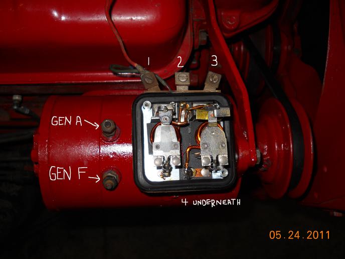
Here's my problem: I don't know which terminals on the VR are which! I see no markings on it. The photo shows the terminals numbered. If someone can match up the numbers with what they should be labeled I think I would be all set.

Thanks, Jerry
a40868.jpg
 
I am just guessing, so don't connect it up until some one conferms it. #4 goes to A on the gen. If that coil by #3 has the points open, it would be the cut-out so #3 gets battery voltage.#1 should be the field connected to field on the gen. The points should be closed on that coil. #2 would be load which you can leave open, or run a wire to feed the lights. I am unsure about #1&2, but if you put battery to #3 , it should show voltage on #2 also. If not check #1. Look real close to those connections next to the screws. There should be A&F&BAT&L. Wait for John T to respond.
 
Jerry if it is like all that I've had, 1 would be [F] fields, 2 [BAT], 3 [L] and 4 [GEN].
[F on the VR should go to F on the Gen.] and the A on the gen. to Gen. on the VR. I think if you take the screws out of the post on the VR where the wires goes and clean the top of the post close to the VR you maybe able to see the letters. Good luck: Mike
 
I've got a bad VR removed from my Super H that looks same as the one in your photo. Terminal designations vs mine:

1 = FLD

2 = BAT

3 = L

4 (hidden) = GEN

Use with caution however - I'm not certain all mfr's VR's terminals are arranged/labelled the same. Yours MAY be different!
 
Forgot to mention: Use my wiring diagram #2 (link below).

Simply omit the ignition switch/distributor wiring (you will leave your existing magneto kill switch wiring as is...)
VR wiring diagram
 
Just a side note, you need to make sure that the regualtor is grounded good.With the new paint onthat genny, you may havea problem with that.
 
Jerry, my friend Bob M is sharper on IHC electrical then myself but I will toss out my thoughts.

1) The old 4 position LHBD light switches were for gennys that use a Cutout relay NOT a full fledged VR as you have shown. HOWEVER you can still use a full fledged VR just DO NOT run the gennys FLD wire up to that switch, wire it to FLD on that VR. The LHBD can still be used as the light switch only.

2) ARM post on Genny to GEN/ARM on that VR and on most 4 terminal VR's the GEN/ARM is the one hidden underneath,,,,,,,,,,FLD on Genny to FLD on VR,,,,,,,,,BAT on VR wires up to the Load (NOT battery/starter) side of the ammeter,,,,,,,,,(L)oad on VR feeds hot batetry voltage up to the lights and ignition (the switches BAT INPUT terminal). NOTE on cutout relay systems loads like lights and/or ignition got hot battery voltage off the load side of the ammeter as there was no L terminal on a VR.

HOW TO TELL WHICH VR TERMINAL IS WHICH

3) The VR on "many" of those the 3 terminals side by side are BAT LOAD FLD and GEN/ARM is underneath. If you use an ohm meter, BAT or LOAD have NO continuity (open circuit) to the VR's metal case mount while FLD will have a low resistance (maybe near 0 to 3 ohms) to case frame. The ARM/GEN to case may have resistance in the range of 20 to 50 or so ohms as thats the shunt winding of the cutout relay.

The BAT terminal on the VR goes to the VR's cutout relay and thats the one that has the big heavy copper winding around the coil. The FLD terminal is the one that goes to the other VR relay that has the much smaller windings.

NOTE 1 THE VR MUST HAVE A GOOD GROUND CONNECTION TO WORK ........

NOTE 2 POLARIZE THE GENNY BEFORE START UP

NOTE 3 the VR will still work if you do not use LOAD terminal and loads can work if fed off the load side of ammeter (same side wire down to VR's BAT attaches) OR LOAD on the VR

Now this info and Bobs diagrams ought to help you figure what wires where OR MAY CORNFUSE YOU??????????

John T
 

Usually the regulator posts are stamped with the identification. You might need to wire brush them a bit and then use a BRIGHT light, and if your eyesight is like mine, take off your glasses and hold the regulator up to your nose.
 

We sell tractor parts! We have the parts you need to repair your tractor - the right parts. Our low prices and years of research make us your best choice when you need parts. Shop Online Today.

Back
Top