Super A timing followup

CNKS

Well-known Member
In classic view, the post dropped to page 2, it is in the link. Briefly, the timing marks do not line up at TDC. My long explanation in the link is incorrect, as I tried starting the tractor with the timing marks aligned, and again with the piston at TDC. In both cases the engine begins turning and stops, meaning the spark is occuring at the wrong time. This tractor ran before, did not have oil pressure which I corrected by removing the governor and plugging the hole at the end of the oil galley. Obviously I reinstalled the governor wrong. But, I did not find a double punch mark on the cam gear as the service manual said, but single marks on two adjacent teeth, I put the double mark on the governor gear between the two singles on the cam gear, thinking that was the "double" referred to. Wrong. So I'll see what I find tomorrow and report back if I ever get it fixed.
Untitled URL Link
 
I'll be watching with interest to see what you find. The only two of that motor I've ever had down that far, the double punch marks were lined/stacked up on the radius of the gear.

I took a squint at the illustrations in the I&T and they show the same. In the corresponding illustration for the Cub, which has an extra idler gear in addition to all the gears being smaller, the marks were punched around the radius on either side of a tooth or notch on one of the gears.

I suppose it could have varied -- as I said, my experience on it is limited to the two of those motors I've rebuilt. Still, couldn't imagine what any other obvious punch marks would be doing there and, if your flywheel mark is anywhere close, as I'm sure you have it, there shouldn't be anything else around that could be confused with the marks you need.

Mag or battery ignition?
 
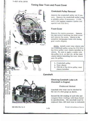
Here's a timing & governor gear pic for a Super C your Super A should be the same. Note the woodruff key is facing to your left. Hal
a32476.jpg
 
Battery. I still don't know why TDC of #1 and the mark on the flywheel are different. Nothing can change unless the crankshaft twists. Perhaps the stamped steel front cover is wrong, but I don't think so. I've already double checked the marks on the cam/governor gear, guess I will do it again. The marks on the crank gear and cam gear match, or I would not have been able to start the engine and find no oil pressure. At least I can do this without removing the axle and steering housing.
 
there could be two marks on the flywheel, one for full advance and the other for TDC. The rumor is that they are both very obscure and need drastic finding.
Put a thin blade screw driver in the #1 plug hole and hand rotate the engine till the #1 piston pushes the driver up until it is 1/2 inch from fully up. Mark the driver and the front pully of the tractor (or a gear if it is apart), with a felt tip pen. Then turn the engine till the mark on the driver returns down to that same spot. Mark the pulley again. then rotate the engine to 1/2 of the distance between the pully marks. Now you know where TDC is located on the FW. It is done with mechanical stops in the plug hole to be very precise, but not needed to just find the mark. Jim
 
Only one mark on my flywheel. Actually TDC using the piston and the flywheel are a lot closer than I thought. I have a small LED flashlight that I use to see the piston. Batteries were low, and absolute TDC was hard to see. With new batteries a lot easier. Once it is nearly at the top, the hand crank can be turned a few more degrees as the piston barely moves at the top of the stroke. This puts the timing marks very close to TDC. I believe that this is why the instructions for static timing say something like "crank until you are on the compression stroke and continue cranking until the marks line up". Difficult to get it perfect looking at the piston, but it is close.
 
El Toro, would you look at your GSS 1295 manual and see if the two marks on the governor gear fall BETWEEN the two marks under adjacent teeth on the cam gear -- the diagram you provided is too fuzzy on my computer to make it all out. I don't see any other way it can work. At some point in time the double marks on the cam gear were separated to adjacent teeth as mine are. My manuals show a double mark, one above the other on the cam gear, my cam gear is not like the ones in my manuals.
 
In the absence of a reply, I've looked in my GSS-5031 for the 113.

For the governor side of the cam gear , they describe,

"" . . . and two punch marks on a tooth of the camshaft gear should line up with two punch marks between teeth on the magneto and governor pinion."

HTH. Obviously my recollection in the last post was off on an important point.
 
I need the info from the GSS 1295 from El Toro. Your manual says the same as the service manual. Mine has the side by side marks and no double mark on the cam gear. El Toros is a later edition that covers the Super C--same general principle. But, I think I know what I did wrong. If my correction works I will post back my ignorance. In the process, regardless of the marks, I got the distributer drive out of sync, I think.
 
I may be wrong on this, but I believe the correct marks should be in position next to the governor gear to do the alignment when the engine is turned to #1 TDC. Set your engine at #1 TDC . Whether the marks are one each on adjacent teeth or close together between two teeth, just use them.

In any case, after installing the governor, the distributor drive slot should be about 35 degrees off of horizontal. (oriented 2 - 8 o'clock when viewed from the distributor end). If you have that orientation at TDC, you are in business.
 

We sell tractor parts! We have the parts you need to repair your tractor - the right parts. Our low prices and years of research make us your best choice when you need parts. Shop Online Today.

Back
Top