Maybe its not the Generator.

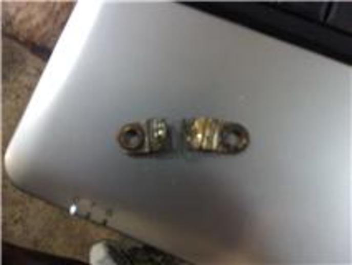
Relooked over my wiring and found this in the ammeter... Would this keep my system from charging? and is this a resistor?
a29502.jpg
 
How did that get IN the ammeter? How did you get it OUT of the ammeter?

Or did you mean it's on the back of the lightswitch inside the electrical box?

There's 2 resistors in there, one for the generator's field circuit, and one for the "dim" lights position.

That appears to be the field resistor, whic, if the wire is broken could cause a
"no low charge" situation, but would NOT affect the "high charge" settings of the switch and would NOT prevent the genny from charging when "full-fielded".
 
In the previous post you indicate that you have a 4 terminal VR. If so it will not need the resistor at all, and any connection to it will be wrong. The L terminal of the 4 terminal regulator supplies the light switch only. YOurs should have only one resistor on it for dimming the lights. If it has two it might be a 4 position switch. Three position switches have only three 3 possible places to set the switch pointer. Full left is off, then dim lights, then bright lights. ODB.
If it is a 4 position sw. it will have L H D B
and no off.

Look at the previous post back several pages. It shows a 4 position switch. It is only used for a cutout only system with lights. It shows two resistors. one for lights, and a Mosdestly broken one for the Low charge position.

The light switch is electrically in two parts. One part has an input for voltage from the L terminal, and one connection for front lights, and one connection for rear lights. It also has a resistor to dim the lights.

The other section of the switch is not connected to any part of the lights. It is used to control charge rate manually. It has (Not now but originally) a wire going from it to the F terminal of the generator. the switch grounded the field to make it work. Direct ground to make full charge on H, and ground through a resistor for L. This wire provided regulation to the gen charge rate. The gen out put (ARM terminal) needed to go through the cutout to charge the battery, but you have a voltage regulator.

Nothing should be connected to the F terminal of the Gen except a single wire going to the VR F terminal.

Nothing should be connected to the charge resistor shown because yours has those resistors built into the VR. Jim
 
I think Im in Bobs camp with what that resistor is, looks like the Field resistor thats used on the back of 4 position LHBD light switches THAT ARE USED WHEN THERES ONLY A CUT OUT ON THE GENERATOR. (3 position switches are for Voltage regulator systtems, see Jims good info) And I agree with him if its open she wont charge in Low charge but still can if all else is right in High charge. Some ammeters use an external shunt and if so and if its open YES that can affect charging BUT ARE YOU SURE THATS A PART OF THE AMMETER???? (again Im thinkin like Bob)

Jim has given you good info on the difference in 3 position switches (used with Voltage regulators) versus 4 position LHBD used with Cutout Relays.

I THOUGHT YOU HAD ALREADY DETERMINED THE GENNY WAS BAD FROM MY TROUBLESHOOTING PROCEDURE????

Heres a part of my Troubleshooting procedure to see if non charging is a genny or a VR problem.

TO DETERMINE IF ITS A GEN OR VR OR CUTOUT RELAY PROBLEM

5. a) VOLTAGE REGULATOR SYSTEM: With the tractor running, temporarily ground the Gens Field post to case. If she charges then but NOT otherwise, the VR may be bad, or a wires missing from VR"s Field post to the Field terminal on the VR, or the VR isn’t well grounded.

b) IF IT’S A CUTOUT RELAY SYSTEM and she charges only if you dead ground the Field but NOT otherwise, its either a bad switch or the switch isn’t well grounded or else the wires bad or open from the Gens Field post up to the switch. INSURE THAT GOOD SWITCH GROUND AND WIRING

6. If she still don’t charge, leave the Field grounded and jump a wire across from the VR or Cutout Relays BAT terminal over to its GEN terminal (jump by passes the cutout relay) and see if she charges. If then but not otherwise, a VR"s cutout relay isn’t working correct (maybe points burned/carboned) or a Cutout Relays NOT working or not wired correct.

7. With the 2 steps above, you have basically by passed the VR or Cutout relays functions, so if she still don’t charge, you"re left with a bad battery or wiring or the Gen itself.

8. MOTOR TEST. You can Motor test the Gen. If its grounded and you remove the belt and apply hot battery voltage direct to its ARM Post and have the Field Post dead grounded to frame, it should motor n run well (Armature n Brushes and Commutator likely okay). Then, if you next remove the Fields ground and it speeds up some, the Fields probably good. If it passes both those tests, it should charge, and if not, it may be a wiring or battery or grounding problem. The hot battery voltage may be taken off the VR"s BAT terminal or the starter post or the battery itself for this test.


You should already have this but heres my complete troubleshooting procedure. You need to determine what you have (3 or 4 position switch and VR or cutout relay) then work through my procedure then post abck your findings and questions so we can help

http://www.ytmag.com/cgi-bin/viewit.cgi?bd=farmall&th=665110


John T
John Ts Troubleshooting
 
Thanks John, and I stand corrected it is the resistor on the light switch. Like I've said I have the 3 position switch(it has the off,dim,bright) But i have the four terminal cutout. I have checked the wiring and it looks all good. I have the right and i did the test and it is my generator. I cleaned the brushes and everything in the generator but still no luck. It polarized right also according to your procedure and still no luck. So I'm going to take it to a local electric shop and have them look at it. Thanks again.
Keith
 
The 3 position Off Dim Bright IS THE ONE YOURE SUPPOSED TO HAVE WITH A 3 OR 4 TERMINAL VOLTAGE REGULATOR

If the genny isnt charging and its NOT the VR's fault (as my procedure above can determine) then the common problems are brushes or brush hold down springys or bushings/bearings or an open or shorted field

Best wishes, let us know

John T
 
heres one other thing to check on the genny. i fought my h for a while with a no charging problem. rebuilt genny, new vr, all new wiring. genny tested good at the shop, would not charge on the tractor. even grounding the field. janicholson had me isolate the brushes from the armature with some cardboard and test the f an a terminals against the genny chassis. found a dead short. the bakelite insulator on one of the posts was cracked, when you snugged down the nut on the post with the wire attached it would short out resulting in a no-charge. at the genny shop the short would not show up.
 
With respect!! Terminology is critical in word based diagnosis, so this may help.
All generators must be disconnected from the battery when they are not turning. This prevents the battery from draining back into the wires in the generator. This device in pre-solid state systems was a cutout relay. It connects when the gen makes more volts than the battery, and disconnects when the gen voltage drops a volt or two below bat voltage. It is pretty much a stand alone device.

For cost reasons the IHC decision makers chose a cutout relay with an internal resistor that could be used by tractors with no lights (lighting systems were an option at the time) to maintain the battery with a modest charge rate.

This fixed resistor is present in the cutout relays of the tractors equipped with lights. it is not used (terminal left disconnected) the tractors with lights used a charge control on the 4 position switch allowing L charge rate (same as the resistor in the Cutout) or a High charge rate which charged higher rates for recharging when restarting the tractor multiple times, or when in either of the lights on positions.

It is also necessary to use a cutout relay inside a voltage regulator, so that era mechanical regulators like yours have a cutout relay built into their design. There is also a voltage control relay in the same housing. It is controlling the voltage output of the generator.
It is connected to the cutout only because there is one winding (going to the Bat terminal) from the contacts of the cutout. This allows the voltage relay to react to high current loads and limit the current by reducing voltage. (generators are not self regulating on current, and are best regulated this way, or with an additional relay specifically designed for current regulation.
Your metal box has four terminals and is a voltage regulator. If it had three, it could be either a cutout with only a cutout being used (F terminal not connected) or a cutout and fixed field resistor (if your tractor had no lights).

There are Delco voltage regulators used on some IH installs (more recient) that have only three terminals but are true regulators) they do not have the L terminal. They are also modest in size and can be confused with the older cutout box. Part numbers will spell the difference between them (or they will be OEM on equipment with three position light switches).

Nice and confusing is it not.

Jim
 
Not a resistor.Its called a shunt.Your ammeter is really a voltmeter that measures voltage drop across a shunt.You need a new meter.
 

We sell tractor parts! We have the parts you need to repair your tractor - the right parts. Our low prices and years of research make us your best choice when you need parts. Shop Online Today.

Back
Top