
You should upgrade or use an alternative browser.
- Thread starter RTR
- Start date
Janicholson
Well-known Member
If the light switch is not getting power (wired as shown) the wire is bad, or the terminals are bad or the switch is bad or the power is there but the lights are bad or not grounded.
If the switch you show is also the ignition switch there needs to be a diode in the line going to the alt. If it is just a switch, and is just used to energize the alt all is well with it.
The system should not draw 11 amps when it is not running, (or when it is) there may be other issues. Let me know about the switch use. Jim
Janicholson
Well-known Member
Make sure the wire going to the light switch is good.
Here is a test. use a marker or instrument light, (bulb) and pull the Bat wire off of the alt. place the bulb between the wire terminal and the stud, such that electricity can flow through the bulb. It should not light. If it does, the alt has a bad diode in one of the diode trios.
If it does not, make sure the bulb does light if it is held to a ground, and the terminal that is disconnected. If it does, reattach it. If it does not, there might be a problem with that wire, or its connections, or the amp meter connection. Jim
TractormanNC
Member
"ammeter reads 11 volts" indicates some sort of misunderstanding as Jim says.
1) Ifff thats an ammeter (NOT a voltmeter) there should be near equal voltage on BOTH sides with respect to frame ground. An "ideal" ammeter has zero resistance through it while even a real one has extreme lowwwwwww resistance sooooooo the voltage on BOTH sides hould be hot and about the Same to frame ground. Sure it NOT a voltmeter as an ideal one of those has infinite resistance??? Whats it face say and what are the numbers/values????????/
2) Ifffffff theres no voltage on that side of ammeter the switch CAN NOT EXCITE THE ALTERNATOR MAKING HER CHARGE !!!!!!!!!!!!!!
3) Ifffff that switch is ONLY to excite the alternator and does NOT serve any ignition switch for a coil ignition (you state its a magneto distributor which isnt kosher, which is it, mag or batetry powered coil ignitiion???) theres no need for any diode in that line buttttt Id still install a safety 10 ohm current limiting resistor in series to the alternators excitation circuit.
4) Ifffffff youre really getting an 11 amp discharge when that switch is pulled there may be bad alternator diodes. Most alternators use Neg ground so I hope you hooked your tractor battery up that way??????? Butttttt if theres no voltag eon that ammeetr terminal Im unsure how youre getting such a discharge???????
This is hard to do over the net since we arent there with our eyeballs and a meter ya know but we try our best. So far things just arent adding up from what you say ???????
John T
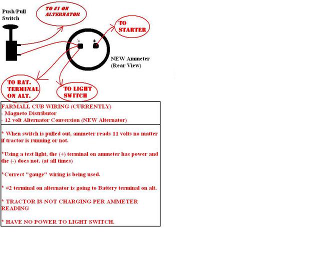
OK. Is there a difference between a volt meter and an ammeter?? If it helps you any, this one reads from 0 - 20 or 30. Its home position is at the 0 to the far left unlike some of the others I've seen which are in the middle.
I can start the tractor, and the meter reads NOTHING. I can pull the switch, and it will read approximately 11. Rev the engine and it doesn't change a bit. Push the switch back in and it reads Nothing once again.
The diagram I drew is labeled as it is on the actual meter, LOOKING FROM THE REAR.
I am so sorry that I am frustrating you guys. I have never "purchased" a charge meter because all of my other tractors had potentially working ones. Therefore, I do not know the differecnce between a volt meter and an ammeter (if there is one).
Yes, I do know that both terminals on the back of the meter should have a "hot" connection, and this one doesn't.
The tractor has NEG ground battery, and has a Magneto Ignition.
An "ideal" ammeter is a series pass through in line current monitoring device with ZERO ohms resistance. It usually has 0 in the middle and then maybe 20 to 30 amps on either side to indicate + charge or - discharge battery current
A "ideal" voltmeter is a paralell divice used to measure voltage drop and has infinite resistance. They usually start at 0 on the left side then go to say 15 to 20 or so volts full scale on the right.
YOU NEED AN AMMETER
When you said one side had voltage (I assume to frame ground) while the other did not that made me think its NOTTTTTT an ammeter and why its not working as you intended. If theres no voltage on the side to teh alternator IT CANT EXCITE THE ALTERNATOR TO MAKE IT CHARGE.
If its a voltmeter and one sides on the battery (via cable at starter) when you turn the switch youre using the alternator as the ground return (it has some resistance) and you may be measuring 12 battery volts less the drop and getting that 11 volt ?? reading
Its either a bad ammeter (its open not a near short) or a voltmeter Ima thinkin since any ammeters Ive seen have 0 in the middle notttttttt on left side like most voltmeters Ive seen.
Best guess:::::::: Its a voltmeter and youre using the alternator as ground
Im interested in what Jim N or Bob thinks of all this??????????????
John T
If you wanan keep it (instead of an ammeter) and its indeed a voltmeter as I suspect post back and I will tell you how to wire it
John T
(quoted from post at 06:55:11 11/15/10) NOT to worry mate, sure Id prefer an ammeter but a voltmeter dont hurt nuttin and some use them on tractors buttttttttttt you have to wire it different then shown.....
If you wanan keep it (instead of an ammeter) and its indeed a voltmeter as I suspect post back and I will tell you how to wire it
John T
WOW! Thank you so much!
If it is ok, I would like to keep the Voltmeter (just this 1 time) because I've already bought it, and I chose this one because it had a nice chrome bezel and a nice white face gauge. It really looks great against the new red paint.
If you don't mind, please send me an email on how to wire it up. I am going to Tyler, Texas for a couple days for a job interview with Halliburton and will not have access to this. If you send it to my email, it will be waiting on me when I return.
Just keep in mind that I have the 12 volt alternator conversion as well as the magneto ignition.
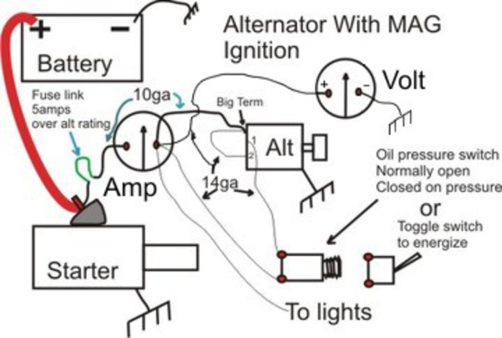
You could wire a switches BAT INPUT (12 gauge is plenty big enough) fed off the big battery cable where it attaches to the starter switch/solenoid input.......have its swtiched OUTPUT wired to + on the voltmeter........the voltmeter - wired to case frame ground........another wire off the switches switched OUTPUT with an in line series 10 ohm resistor down to the Alternators 1R Excitation terminal. Turn it on and the voltmeter will read battery voltage plus excite the alternator and turn off when not running.
Usually loads like lights are fed off the load side of an ammeter but if you have no ammeter Id wire a 20 amp in line fuze and 12 gauge wire again from the big battery cakle at starter switch/solenoid input up to the BAT INPUT light switch terminal.
The alternators big main output can wire with 10 gauge wire to the batery cable identified above. If its a GM 10 SI 3 wire alternator its other small 2F terminal wires to its big main output post.
Nuff said, this assumes you have a voltmeter
John T
Janicholson
Well-known Member
Question: if the battery becomes or is fully charged, doesn't the ammeter charging amps drop off as well? Is it kinda like a battery charger where it drops down to low amp charge? The alternative would be for a 30 amp alternator to always put out 30 amps whether needed or not. I'm thinking their is something in the alternator that works like a battery charger.
John T"
Thanks John. So technically a voltmeter showing 12.6 to 14.7 volts will show it is charging but not the rate of charge in amps which the ammeter does. I may pull the non working fuel guage out of mine and put a voltmeter in so I've got both. Then I can track current flow and the condition of the battery and alternator at the same time.
Janicholson
Well-known Member
(quoted from post at 08:29:44 11/18/10) Unless the tractor sits for 3 or 4 months, the gauge will not draw down the battery. It is a very high resistance. Jim
Thank you soo much for all of the help guys. To me it sounds like it would be a good idea to put a "Master Switch" or a Quick Disconect in that turns off the battery power. Or would the toggle in-line between the gauge and the ground wire do the trick just as good??
Similar threads
- Replies
- 4
- Views
- 316
- Replies
- 4
- Views
- 187
- Replies
- 30
- Views
- 889
- Replies
- 6
- Views
- 457
We sell tractor parts! We have the parts you need to repair your tractor - the right parts. Our low prices and years of research make us your best choice when you need parts. Shop Online Today.
Copyright © 1997-2024 Yesterday's Tractor Co.
All Rights Reserved. Reproduction of any part of this website, including design and content, without written permission is strictly prohibited. Trade Marks and Trade Names contained and used in this Website are those of others, and are used in this Website in a descriptive sense to refer to the products of others. Use of this Web site constitutes acceptance of our User Agreement and Privacy Policy TRADEMARK DISCLAIMER: Tradenames and Trademarks referred to within Yesterday's Tractor Co. products and within the Yesterday's Tractor Co. websites are the property of their respective trademark holders. None of these trademark holders are affiliated with Yesterday's Tractor Co., our products, or our website nor are we sponsored by them. John Deere and its logos are the registered trademarks of the John Deere Corporation. Agco, Agco Allis, White, Massey Ferguson and their logos are the registered trademarks of AGCO Corporation. Case, Case-IH, Farmall, International Harvester, New Holland and their logos are registered trademarks of CNH Global N.V.
Yesterday's Tractors - Antique Tractor Headquarters
Website Accessibility Policy