Wiring Problem - help me read the schematic

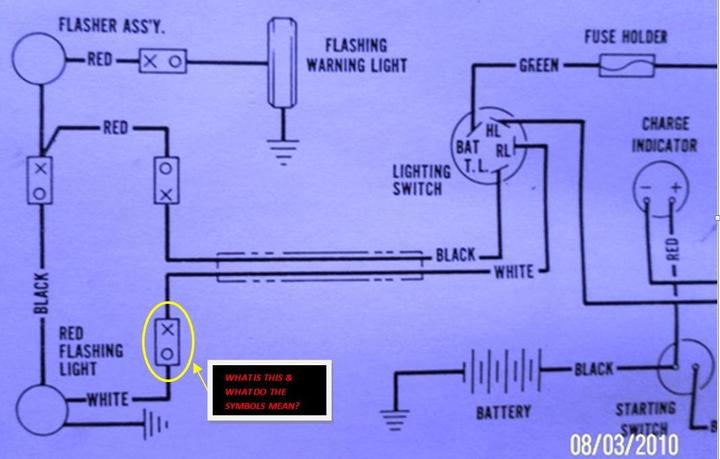
Pictured below is a wiring schematic for a Farmall/IH Cub tractor. I am actually working on a 1976 140 tractor, and this wiring schematic should be approx. the same. This is the only one I had at my disposal, although I understand there are 140 diagrams on here.

My question/problem is that my 140 caught fire and burnt completely, and I am re-doing the tractor. I am putting the original hazard lights on the fenders and the rear worklight/tail light back. However, I don't care to have the turn signals, so I am not going to put those on there. This diagram for the Cub seems to be what I am needing, however I don't understand anything it is saying/showing from the light switch to the rear. It just doesnt make sense to me. Look at the picture for more detail, and I will ask questions as some are answered because I have several. Thanks for all of the help.
 
Here is the 1st picture with the 1st question.....
a19717.jpg
 
I've never seen that symbol before. My guess would be that it represents a connector (plug and socket, for example) in the wiring.

Mark W. in MI
 
So basically, with me using "new" wiring; I can omit that symbol and run continuous wire through that/those points??? I may wait for a couple more answers before I procede to next question just to make sure.
 
Why the heck didn't automotive wiring use the same symbols and "ladder" diagrams like industrial equipment? Sure would make it easier for an old guy like me to read :lol: .
I too would suspect they are a connector of some sort... no other component would make sense where they are.
 
I sort of assumed it was a type of connector, but is it mandatory for the whole system to function?? Or is it listed just for originality, and in case the "restorer" or mechanic is dealing with the exact factory set up? Do you think I could simply run a continuous wire through these "connections" until I get to an actual "junction"??
 
Never seen it before, but I'll chime in on the side of them being connectors. Note the o is always on the side toward ground, and the X on the side toward the hot of the battery. Connectors are also suggested by the color of the wire changing on either side of them in several (but not all )cases. No other purpose for them.
 
Ok, next question...

1) what does it mean by "red flashing light". I have never seen any of these tractors to have a red light that flashes. they did come with the orange/amber flashers which are pictured on the diagram at the top. Is this the tail light/work light? I'm really confused.
 
Could be....What are the large "circle" symbols represent at the top and bottom if the one in the middle (to the right of the top one) represents the amber flashing light. Where is the Rear work light/tail light combo???

I'm so sorry, but I am extremely confused as to what it is trying to say in the rear part of the schematic.
 
im guessing you are talking either about the large circle in the left top that is the flashing asembly that makes the light flash, i dont know about the combo, i would think that there would be a way to wire it in but im not positive
 
As several others have replied it indicates a (male "O" / Female "X", or (plug / socket) connect or disconnect point in the wire harness. The female or socket side of the connector is powered from the HOT side of the battery and the male or plug side of the connector is tied to the GRD side of the connector. The female or socket side of the connector is insulated and reduces the chance of the wiring shorting to ground if the connector is separated and touches any part of the tractor frame. The male or plug side of the connector will not short out beause it is connected to the ground side of the connector. You may eliminate this disconnect point and wire from component to component without any problem other than losing the ability to break the wiring at this connection point.
 
WOW!!! I do too. Greenie: could you PLEASE help me understand what is going on from the light switch rearward?? I am assuming you are familiar with what these tractors had as far as lighting...to me something is missing. The tractors had a rear work light that doubled as a red tail light. They also had 2 amber flashing lights on each fender (Cub actually had one). I simply just don't understand what this diagram is saying!! The connector part I am fine on, but other than that......
 
Or anyone for that matter.........Thanks so much for all of your help thus far, and hopefully we'll straigten this out soon. Look forward to your replies!
 
Or anyone for that matter.........Thanks so much for all of your help thus far, and hopefully we'll straigten this out soon. Look forward to your replies!
 
Al, I wish I was more familiar with the lighting setup on the Cub and 140 series tractors. I never owned one but I have a 1976 Cub service manual and it shows the exact wiring diagram that you have pictured. It looks like the Red flasing light at the lower rear on the diagram is a two filament lamp. When the lighting switch is in the RL position the Rear lamp will light as a white work light. With the switch in the TL position the other filament will light a red lens within the rear light and flash alternately with the Flashing warning light that I assume is amber. The Flasher unit is just a thermal set of switch contacts that open and close when current heats the element. Check your light switch and see in what position the Bat terminal is connected to the HL, RL, and TL terminals.
 
Ok, as far as the "flasher" goes for the amber lights to make them flash. Can I purchase one of those at the local automotive parts store? Isn't that a universal item? If so, what do I tell them that I need? Will I need anything else to make it work right, or will I just need to wire it all up?? Thanks.
 
Would anyone out there happen to have this same Wiring Schematic for an International Farmall 140 (1976 model). That is actually the diagram I need, but only had the 1976 Cub diagram handy. I have looked at the one online at the CASE/IH website, but it isn't that good.

The Cub diagram I posted a picture of is from the "blue ribbon manual". Would anyone happen to have one for the 140 out of the "blue ribbon manual" that they wouldn't mind sharing??? Thanks so much for everyones help thus far!!!
 
The circle at the lower left is the combination red/white light. If you don't have the flashing light, you unplug the two connectors on each end of the red wire and plug the two black wires directly together.

The upper left circle is a flasher for the red/amber light.
 
Yes they are standard automotive flashers that you can purchase at any auto parts store, WalMart, many gas stations, Tractor Supply, etc..

Wiring the lights is pretty easy. Just take it one wire at a time, one light at a time. It appears that you're trying to get a mental picture of the entire system in one fell swoop and it's confusing the heck out of you.
 
This question is to Jim Becker (or anyone else who can answer it):

How do I know if I have the red flashing light?? I have the rear worklight that has a sealed beam bulb with a red colored backing on the bulb. Behind the sealed beam bulb is a smaller bulb assembly that is supposed to "shine through" the large one. What set up is this???
 

I looked at your diagrams on your site, however the 140 diagram is the same one I found on the CASE/IH site. I am looking for one that has the set up for the rear light as well as the 2 amber flashers at the rear. The Cub diagram I had came out of the "Blue Ribbon Service Manual", and I would like to have the one for the 140 that came from the same manual; unless you know of one that is as good or better. THanks so much
 
How do I know if I have the red flashing light?? I have the rear worklight that has a sealed beam bulb with a red colored backing on the bulb. Behind the sealed beam bulb is a smaller bulb assembly that is supposed to "shine through" the large one. What set up is this???
I think that is an error in the diagram. The word "flashing" doesn't belong there. You just have a red/white combination lamp.
 

Thank you Jim!! That is what had me confused. Does anyone out there have a wiring schematic for the 1976 140 like the one I posted for the Cub?? The one on CASE/IH isn't the right one for that year model with the flashers. My I&T manual doesn't have a good one either. Thanks so much.
 
You bet. Connectors are mainly for ease of installation and ease of maintenance. If those aren't very important, you can go without them.
 

We sell tractor parts! We have the parts you need to repair your tractor - the right parts. Our low prices and years of research make us your best choice when you need parts. Shop Online Today.

Back
Top