Farmall 450 (Gas) Wiring

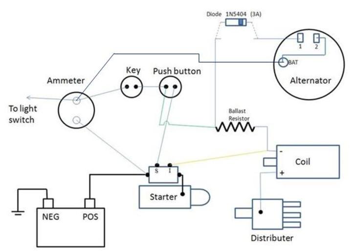
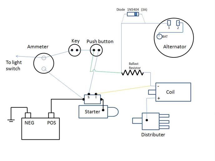
OK, having some issues on the wiring aspect of things. I originally had a Generator, just replaced it with a 3 wire Alternator, a generic brand Delco. I wired it up with a diode in the picture below, I measured the voltage while it was running and was getting ~14v across the battery. Thought that was good. Turned off the KEY, the tractor stayed on. I had to pull the #1 wire from the Alternator to get it to turn off. Started reading, and found out I needed a DIODE, put it where the picture told me to and then Turned the KEY to ON and the Diode promptly went up in smoke. Here is what I have going on. Please tell me what connection is wrong, and where the diode needs to go.

Thanks
Tony
a12238.jpg
 
Well in your picture you have the diode wired in parrel to the wire from the #1 terminal to the ignition switch and if that is so yep it will not work. The diode needs to be in line as in cut the wire under the diode and it will work the way it should. You do also have it hooked up wrong on the coil and you need to have the + side of the coil hooked to the ignition switch and the - side to the distributor
 
As old says and also a 10 ga wire from the BAT terminal of the alt to the ammeter terminal which has the wires to the light switch and the key switch.
 
Where you wired the diode IS FINE THATS NOTTTTTT THE PROBLEM. BUT we dont know for sure if its wired same as the diagram remember??????

I usually wire them to the IGN output of the key ignition switch butttttttttt thats the nearly same point electrically as the hot voltage INPUT SOURCE to the push button as you have it and the switched input to the ballast and coil. i.e. the same voltage is present on the key switch output as the push switches input and input to coil/ballast........

WHERE YOU WIRED THE DIODE HAS THE SAME AFFECT AS IF ITS WIRED RIGHT TO THE COIL OR DIRECT FROM THE IGN OUTPUT ON THE KEY SWITCH

Soooooo now that where its shown IS FINE (provided your diagram is same as on the tractor) lets diagnose other possible causes

1) Do you have a 10 Gauge wire from the Alternators big main output stud up to the Load side of the ammeter??????????

2) The diode is polarity sensitive and the Neg Cathode (banded as shown) end must wire to the Alternator SURE YOU HAVE OT RIGHT???? It should pass current to the alternator to excite it when the switch is on BUT NOT allow reverse current to flow out of the alternator to power the coil when the key is off (prevents backfeed so engine dont run when you turn of key)

3) If she ran when ign was off, the coil was getting a voltage backfeed from the alternator either because the diode was wired backwards or was bad or it wasnt wired as shown.

4) SURE YOU HAVE THE BATTERY AT NEG GROUND???????????????????? If not you may have fried the alternator

Also for Neg ground the coils - wires to the distributor while its + gets ignition switch voltage.

CHECK FOR POLARITY OF BATTERY,,,,,,,,POLARITY OF DIODE,,,,,,,10 GAUGE WIRE FROM ALTERNATOR UP TO AMMETER

Hopefully neither the alternator or diode have been fried.....

John T
 
Rich, where he as the diode wired IS NOT THE PROBLEM. Even though its not where we often wire them (on key switch output or coils input) where he has it has the same affect, to excite the alternator ONLY once we turn the key on as its then a hot battery voltage source. The nearly same hot battery voltage source is equal at the Keys Output,,,,,,,,,,The push switches Input,,,,,The ballast Input. i.e.where he has it should work fine I HOPE HE DIDNT HAVE WRONG POLARITY AND FRY HIS ALTERNATOR???????

See my post above, hope this helps, hope all is well with you in Missouri

John T
 
Thanks for the input.

Just so we are on the same page, the Diode was not in the circuit when the tractor did not turn off. I read online somewhere that I needed a Diode so I put one in. I did cut the wire below it. Once I did that, and turned on the Key, the Diode fried. I never actually started the tractor once I put the Diode in it. I was worried...

I do have 10 gauge wire from the BAT on the Alternator to the POS side of the Battery.

I was wondering about the Coil, looked backwards to me, but it always ran fine for me before I messed around removing the alternator. (Could that be whats killing the diode??)

Yes the Body of the tractor is NEG.

Thanks
Tony
 
Tony:

1) YOU SAY: I do have 10 gauge wire from the BAT on the Alternator to the POS side of the Battery.

That wire SHOULD run to the Load (NOT Battery)side of the ammeter NOT direct to the Battery. If you wire it direct to the battery (Supply side) of Ammeter, the ammeter isnt registering charging current out of ammeter to battery. IM NOT SURE IF I GOT THAT CORRECT IN MY POST ABOVE, SORRY I WAS IN A HURRY. Theres only 1 wire on battery supply side of ammeter, it wires to + of battery, the other Load side feeds loads (lights and ignition) PLUS wires to genny or alternators output

2) YOU ASK: I was wondering about the Coil, looked backwards to me, but it always ran fine for me before I messed around removing the alternator. (Could that be whats killing the diode??)

The coil will still produce a spark if at reverse polarity, but its not as good or efficient as if its wired correct to match battery polarity i.e. for Neg ground the coils - wires to distributor. NO thats NOT whats killing the diode. Excess curent can kill a diode, but that would mean the alternator has a problem??? Normally the excitation circuit would be vey low, less then an amp even UNLESS THERES A SHORT??? You sure the lil No 1 (Excitation) terminal was used for excitation?? and 2 (Sense) wired to big main output...

Is that a Delco 10SI???

John T
 
On all my 12 volt systems the diode I put in is right there at the alternator so as to be able to see it and know it is still there and not broken which I have seen happen. I use heat shrink on them also to cover them up. But for a diode to smoke that is a new one on me unless it was not rated for the load. My self I use the radio shack 27601661 since it is a 6amp 50VPX and 400APX surge
 
If your Alt is a 10SI Dewlco (and good, as new ones can be bad) the diode (as pictured with the wire cut and placed as shown with the band end as shown, should be OK. If it was without the diode (as befor it didn't melt the wire!
I think that it could have been either a bad diode, or a bad regulator in the alternator.

Do turn the coil polarity around. Jim
 
A bit of my reasoning:
If the diode were in backwards, the alternator would not get exciter voltage.
If it were in correctly it would work as intended. Either way a bad internal regulator, or a bad diode would cause the problem. Jim
 
Thanks again for more info.

Yea, when I get in a hurry I forget to add stuff... like this morning and last night (picture was missing a wire from the BAT to the Ammeter.)

Meant to say:
I do have 10 gauge wire from the BAT on the Alternator to the Load side of the Alternator.

Good to know that the Coil thing will not kill anything, was afraid to change it, but now I will so that everything is wired correctly.

Just so I am understanding correctly..
Both the #1 and #2 need to be at the 12v when the Key is switched on? Is that a correct statment?

And the Diode is in the correct position, sounds like Yes, but could be somewhere else also...?
Should I get a bigger AMP rating (like the 6Amp mentioned?) How many AMP should be going to the #1 position?


Thanks
Tony
a12266.jpg
 
Just so I am understanding correctly..
Both the #1 and #2 need to be at the 12v when the Key is switched on? Is that a correct statment?

YES, No 1 is at 12 from the key, (when ON) No 2 is at 12 (always) as its connected to the ammeter

And the Diode is in the correct position, sounds like Yes, but could be somewhere else also...?

Its fine where it is, I normally wire them direct to the output side of the key switch, but your at the same point electrically.


Should I get a bigger AMP rating (like the 6Amp mentioned?) How many AMP should be going to the #1 position?

A 3 amp should suffice, theres less then an amp to excite the alternator UNLESS theres a problem ??????????


John T
 
Yep, thats a good place to "physically" place them, his other diode end will still work as he has it shown electrically since the voltage on the push switch input is near the same as the output on the key or even the input to his ballast. Im afraid he has either an alterntor problem or else the diode is bad

John T
 

We sell tractor parts! We have the parts you need to repair your tractor - the right parts. Our low prices and years of research make us your best choice when you need parts. Shop Online Today.

Back
Top