I don"t really know where to start explaining my problem....so bear with me as I attempt to describe my woes.
I have been trying to figure out why my tractor suddenly quit running. I fired it up a few days ago and after about one minute, it died as if it ran out of gas.
I took the fuel line loose, sediment bowl and finally removed the carburetor and went through it. While I had it off, I even put a kit in it. That didn"t solve a thing.
Hmmm, says I.
So, I go to the other side and begin inspecting the ignition. Hot wire is fine to the coil.
Inspecting the points, I find them pitted pretty badly and they only have about 15 hours run time on them. The plug wires were pretty sad as well, so, in went all new ignition components....everything. Points set at .020, plugs at .023 as per the book. The new wires went back on according to the book schematic 1-3-4-2.
Still, the tractor refuses to start. Thinking there was a possibility of having the wires on wrong....I even advanced them all on socket ahead and then went in the other direction. Of course, I got backfires and such....but that proved to me the wires were on right to begin with.
I then hotwired it.....ran a wire from the positive battery post to the coil....once, it seemed like it wanted to fire.
Hmmm, again.
This tractor had been converted to 12 volt before I got it and I had never had any problems, therefore I never messed with the wiring.
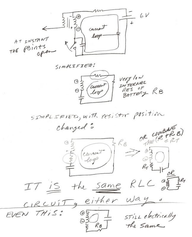
I found it still has a 6 volt coil. The battery wire has been ran to a ballast resistor and from there to the coil negative post and the positive coil post to the distributor.
I am no electrician....but I would think the 12 volts being ran to the resistor, hypothetically anyway...should reduce it down to 6 volts. Being a positive charge......shouldn"t the ballast wire then attach to the positive terminal of the coil and then the negative coil post go to the distributor?
I talked this over with a friend and he said I should have a 12 volt coil with the positive battery wire ran to it"s positive post and then ballast resistor going between the negative coil post and the distributor.
Am I confused? Damn right, I am!
With all the ignition components being fresh EXCEPTING the coil, I cannot fathom why this engine refuses to start, UNLESS the coil is bad.
So, if the coil is going dead and considering the tractor has been converted to 12 volts (battery and alternator).......what volt coil do I need and how should the ballast resistor be wired to the coil?
If all this is clear as mud, I apologize. It"s the way I knew to explain my problem. Thanks.
I have been trying to figure out why my tractor suddenly quit running. I fired it up a few days ago and after about one minute, it died as if it ran out of gas.
I took the fuel line loose, sediment bowl and finally removed the carburetor and went through it. While I had it off, I even put a kit in it. That didn"t solve a thing.
Hmmm, says I.
So, I go to the other side and begin inspecting the ignition. Hot wire is fine to the coil.
Inspecting the points, I find them pitted pretty badly and they only have about 15 hours run time on them. The plug wires were pretty sad as well, so, in went all new ignition components....everything. Points set at .020, plugs at .023 as per the book. The new wires went back on according to the book schematic 1-3-4-2.
Still, the tractor refuses to start. Thinking there was a possibility of having the wires on wrong....I even advanced them all on socket ahead and then went in the other direction. Of course, I got backfires and such....but that proved to me the wires were on right to begin with.
I then hotwired it.....ran a wire from the positive battery post to the coil....once, it seemed like it wanted to fire.
Hmmm, again.
This tractor had been converted to 12 volt before I got it and I had never had any problems, therefore I never messed with the wiring.
I found it still has a 6 volt coil. The battery wire has been ran to a ballast resistor and from there to the coil negative post and the positive coil post to the distributor.
I am no electrician....but I would think the 12 volts being ran to the resistor, hypothetically anyway...should reduce it down to 6 volts. Being a positive charge......shouldn"t the ballast wire then attach to the positive terminal of the coil and then the negative coil post go to the distributor?
I talked this over with a friend and he said I should have a 12 volt coil with the positive battery wire ran to it"s positive post and then ballast resistor going between the negative coil post and the distributor.
Am I confused? Damn right, I am!
With all the ignition components being fresh EXCEPTING the coil, I cannot fathom why this engine refuses to start, UNLESS the coil is bad.
So, if the coil is going dead and considering the tractor has been converted to 12 volts (battery and alternator).......what volt coil do I need and how should the ballast resistor be wired to the coil?
If all this is clear as mud, I apologize. It"s the way I knew to explain my problem. Thanks.