Generator on M

Our Phone System is Down!

Please use the Contact us Form

We are working to resolve the issue ASAP! Thanks for your patience!

Bill in IL

Well-known Member
Trying to get my generator to charge properly on a farmall M. I spent some time reading John T's troubleshooting guide and working with it last night. Is a 3 brush generator with a 4 terminal voltage regulator.

I show good charge on the ampmeter and voltage of 6.7 coming out of the generator with it running at half throttle. Problem really comes in when I turn on the lights. Then it cannot keep up and discharges system voltage drops to battery voltage (6.3) so it tells me the generator is working somewhat and the VR is working too. I just put new belts on 2 weeks ago and they are tight.

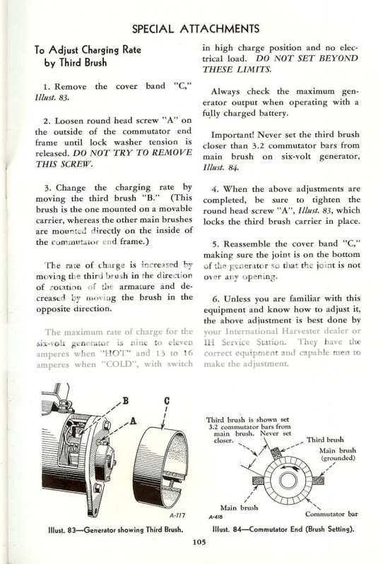
Why can I not get any more current out of this thing? I cleaned the commutator with 400 grit paper and brushes look in good shape. How does the 3rd brush affect charge output and how do you adjust it?

Should my lights be coming off the Load terminal on the VR and not off the Batt terminal as it is now?
 
The third brush needs to be moved closer to the next closest brush to increase the output. There is a slotted screw head visible on the outside of the rear frame. It will be located to the left of center. Loosen that screw and then you can move the brush. The book I have says to move the third brush no closer than 3.2 commutator bars from the next brush, but I had to adjust mine much closer before I noticed an improvement.

It is a guessing game, move that brush a little at a time and test the results. Move it more if needed.
 
To the other part of your question, yes, the lights should be running off the L(oad) terminal on the regulator. In theory they look like parallel circuits, so I don't know what difference it would make, but then I don't grasp all the mysteries of what all happens in the internals of a regulator, either. I'd try the simple step of switching the lead for the lights over to the L terminal first see if that fixes it before I got into the third brush.

Follow the link to the very useful page, bookmark it, then have a look at #2 and #6.
BobMs Most Excellent Wiring Diagrams
 
(quoted from post at 11:00:18 09/22/09) To the other part of your question, yes, the lights should be running off the L(oad) terminal on the regulator. In theory they look like parallel circuits, so I don't know what difference it would make, but then I don't grasp all the mysteries of what all happens in the internals of a regulator, either. I'd try the simple step of switching the lead for the lights over to the L terminal first see if that fixes it before I got into the third brush.

Follow the link to the very useful page, bookmark it, then have a look at #2 and #6.
BobMs Most Excellent Wiring Diagrams
he difference that it makes is that any loads connected to load terminal will receive generator current directly from the generator without the regulators current sensing circuits knowing anything about it. In other words the current regulator function will ONLY apply to the generator current going into the battery, totally independent of any loads being supplied via the L (load) terminal. Imagine a lighting load so large that the lighting current plus the battery charging current is so large when combined that it exceeds the regulators current limit. If those loads are connected to the battery, this combined load is the way the regulator senses and controls generator maximum current & would cut back on field current & thus generator output to stay within the design current limit. However, when those lighting loads are connected to the load terminal, the regulators current sensing function does NOT see that current, rather it sees only the current applied toward re-charging the battery and allows the generator to do its best to support both loads.
The scheme appears to do nothing to protect the generator from current overload, which may be why it fell from grace over the years.
 
I tried that last night actually ran a wire to the load terminal for the lights. It didn't change the output any so I put it back how it was. The thing I was wondering then.... You won't have lights when the tractor is not running. Is it maybe suppose to keep you from draining the battery?
 
Thanks Rusty I will give it a look again. Didn't see anything like that on the back of the unit last night though. Were some of them adjusted throught the "commutator window" under the dust cover?

How do you define next closest brush? Looks to me its half way between the 2. Is it by order of rotation? Guess the slot will only allow me to go one way.
 
Bill, the purpose of that 3 brush genny is so you can regulate the gennys max output current. They were used more on the older Cutout Relay systems versus the full fledged Voltage Regulators.

The closer the third adjustable brush is to the fixed brush right next to it THE MORE THE CHARGE. The other fixed brush is the fixed grounded brush which is like 180 opposite across from the other fixed Armature brush (ie one next to third adjustable). Some Delco gennys say no closer then 1.5 commutator bars while others say 2.5 etc

HOWEVER when the full fledged VR is used theres less worry of overcharging and I usually advise people to set the third brush to max charge since the VR still protects the genny moreso then only a Low/High light switch did.

(L)oad Terminal: On the 4 terminal VR loads like lights and ignition are best fed from the VR's L terminal versus the Load side of the ammeter (like on 3 terminal VR systems). That way less current has to flow through the VR's internal Cutout Relay and they are said to do a more precise job of preventing overcharging. While it will stil work if lights are fed from the ammeters load side (which wires down to VR BAT terminal) and the L terminal is ignored, I ADVISE YOU USE THE L TERMINAL

NOWWWWWWWW see what she does if you dead ground the Gennys FLD post?????????? If she charges okay then but NOT otherwise, the problem may be the VR ORRRRRRRRRRRRR VR needs adjusted ORRRRRRRRRRRRR the VR isnt well grounded

NOTE If the L terminal is used and its a good battery the system may be working fine AS IS. Once the batetry is charged up its NOT supposed to keep pumping more high amps into the battery, and consider the gennys current used to run lights and ignition is now going DIRECT TO THEM AND ITS OUT OF THE CUTOUT REALY CIRCUIT.......

If you just gotta have more amps (Im not sure that you really do) I would adjust the third brush closer to the fixed one beside it and insure the VR has a good ground.....

best wishes

John T
 
Where does the VR get its ground from?

I see a braided wire that comes off the VR to the Generator. Is that the ground wire grounded directly to the case of the gen? I even ran a wire from the case of the Gen to the block to help aid the ground for the gen.

I also did ground the field terminal with the lights on and it still discharges. I am only trying to run the stock lights on the M 2 in front one in back so the gen should be able to handle those 3.
 
Thanks, JMOR.

Between you and the regular electricical contributors around here, I just MAY get the hang of them one of these days!
 
Just to add something here to the very good explanation of the combination current voltage regulator, not all 3rd brush generators had the adjustable option so you cannot move them. And the load terminal on regulator is live all the time same as battery terminal on regulator so you will still have lights without engine running. Then also realize when moving 3rd brush closer to main brush you are increasing current flow through field, thus through voltage regulator points and therefore may cause short life of the points in regulator. Later new replacement generators were of the shunt wound version(two brush) and performed much better.
 
(quoted from post at 13:03:26 09/22/09) Thanks, JMOR.

Between you and the regular electricical contributors around here, I just MAY get the hang of them one of these days!
ou are welcome. When opportunity presents itself, I try to remember to pass information along. Somebody has to remember it for the future........all us old ones won't be here forever.
 
(quoted from post at 13:33:50 09/22/09) Just to add something here to the very good explanation of the combination current voltage regulator, not all 3rd brush generators had the adjustable option so you cannot move them. And the load terminal on regulator is live all the time same as battery terminal on regulator so you will still have lights without engine running. Then also realize when moving 3rd brush closer to main brush you are increasing current flow through field, thus through voltage regulator points and therefore may cause short life of the points in regulator. Later new replacement generators were of the shunt wound version(two brush) and performed much better.
Yes, as pete23 said..........my SMTA has a non-adjustable 3rd brush generator.
 
Good advice offered by the other posters below. A couple more thoughts however:

1 – Your observed charging voltage of 6.7 volts is a bit on the low side. 7.1 to 7.4 volts is preferred. (This of course presumes your voltmeter is accurate - it may not be!). Means the VR relay may need a tweak to bring its set voltage up a few tenths.

2 – Assuming stock lamps (with a stock bulb inside each lamp...) a healthy generator and regulator will not supply adequate current for the lights and ignition until the engine’s running at about 2/3 throttle. Running slower has the lights consuming more current than the generator can put out. The battery then makes up the difference by slowly discharging. The only way then to make it charge is to throttle up.
 
The VR ground is usually its metallic case,,,,,and that can get its ground via its mount to the case of the genny (maybe a braided wire depends on VR manufacturer) ,,,,,,,,and then the genny grounds to the tractor via its mounting bolts.

John T
 
How do you go about tweaking up the "set" voltage in the regulator? I do trust my meter to be accurate. Maybe that is all my problem is.

Planning also to hook up to the load terminal of the VR.

I also did run the tractor up to full throttle with no change. Did most of my testing about about half thottle due to not noticing much difference after that. Lights are stock lamps that don't put out much more light than a candle on a good dark night so the generator should be able to keep up with them.
 
(quoted from post at 15:58:45 09/22/09) How do you go about tweaking up the "set" voltage in the regulator? I do trust my meter to be accurate. Maybe that is all my problem is.

Planning also to hook up to the load terminal of the VR.

I also did run the tractor up to full throttle with no change. Did most of my testing about about half thottle due to not noticing much difference after that. Lights are stock lamps that don't put out much more light than a candle on a good dark night so the generator should be able to keep up with them.
Bill, earlier, you said, "I also did ground the field terminal with the lights on and it still discharges." That grounding of the FLD makes the generator provide maximum output, so if that is insufficient, then I don't believe any VR tweaking will get you there.
A little research into my stack of old manuals shows the M generator maximum output to be 9 to 11 amps hot and 13 to 16 amps cold. If that applies to the generator that you have AND if your lamp power is the same as currently listed replacement lamps (30w per headlight and 24 watts rear work light), then it simply can not keep up when hot.
(30+30+24)/6.8v= 12.3 amps. (barely make it w/o work lamp). And I can tell you, that this picture just about fits my experience with my SMTA.
My M manual shows adjustable 3rd brush & adjusting procedure and my SMTA manual states "fixed 3rd brush".
 
Thanks for checking your old manuals. What type of manuals do you have. I only have the I&T manual and it doesn't even mention the Generator.

I have not given up on it yet but raising the output voltage to within an acceptable level of 7.2 volts would lower the current to 11.6 amps.... still barely in the range but it would charge the battery better. I keep having to supplement it bout once a month with the charger or hand crank it once in a while.

When I get outside tonight I want to check it with the ampmeter and see exactly what the output is cause it goes to discharge on the low lamp setting too.

Guess I see why so many convert to 12v. My wd is 12volt and everything is fine there even running a spotlight with the headlights.
 
Well, yes there is a gigantic difference between 11 amps and a 60, 90, even over 100 amp alternators of today. But when those old tractors were built anything beat the hand crank. I have the original manuals that came with relatives M and SMAT and even a IH Model 101 combine. I have & regularly operate the SMTA and the 101. M slipped away. My wife says I'm potential for the "Hoarders" TV show. Here is cover and a generator page.

Farmall_M_manual.jpg


Farmall_M_3rd_brush_adj.jpg
 
Try measuring voltage across the battery after making the connection to the VR "load" terminal and see what you get.

----

If the voltage is still low, it can adjusted by GENTLY bending the spring hanger on the VR relay. Increasing spring tension increases the voltage setting.

But be careful! Only a slight change in tension causes a significant change in voltage. Also make sure the battery is fully charged and the charging system is up to temperature (has been charging for 5 - 10 minutes) before attempting adjustment.

(Note - The VR relay is the one with its contacts held CLOSED by spring tension.)
 

We sell tractor parts! We have the parts you need to repair your tractor - the right parts. Our low prices and years of research make us your best choice when you need parts. Shop Online Today.

Back
Top