Super M Hydraulics - please explain

asbennett

New User
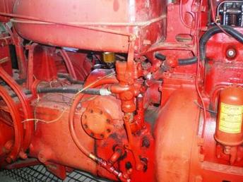
I have a 1954 Super M and need someone to explain the "workings" of the hydraulics for me. The problem is all the books I read and pictures I look at have the hydraulic reservoir under the gas tank. Mine does not have this tank. My hoses run to the transmission body. I cannot find where to check / fill the fluid levels. Also, there is a lever just in front of the Belt pulley on the right side of the tractor. What is this for? Sorry for the basic questions but this is my first tractor.
 
Is your hydraulic pump between the distributor and the front of the engine? Or can you not easily see you hydraulic pump? Are the covers over the brakes sheet metal with one ring of bolts right at the edge? (follow the brake linkage) Or are the brake covers cast iron with bolts that are not on the edge?
 
Sounds like you have a belly pump. You probably have a Stage I Super M, or an M with SM decals. Look at an M manual, it'll tell you about the pump and how to use it. The lever you refer to is the control lever. (My $0.02 worth. jal-SD)
 
I added a photo of the tracor. The pump is not near the distributor. Let me know if you have trouble seeing the picture.
id6134.jpg

id6134.jpg
 
The lever I am referring to is not the Hydraulic control lever, it is the one below the hydra. control lever.
 
You do not have a 1954 Super M. You might have a 1952 or early 1953.

First off make sure that you do NOT have hoses running to a unit located in front of the distributor. What I am about to explain assumes that you do NOT have this live pump. If you do have a live pump, then DO NOT FOLLOW any instructions I list below. Read it for educational purposes only. You will blow something up if you follow my instructions with a live pump installed.

What you have is officially known as the transmission-driven Liftall system. We call it a "belly pump" for obvious reasons.

It's a self-contained system that is driven off the transmission of the tractor. You need to have your foot off the clutch pedal to get pressure. It is not live hydraulics.

There is a fill pipe under the gas tank on the right hand side, in front of the belt pulley on top. Usually there is a dipstick in there, but sometimes they get lost. Sometimes the owner will connect the return from a two-way valve to this pipe.

On the sides, there should be two holes on the left and one on the right (maybe vice versa, I'm working from memory and my head is foggy this morning from lack of sleep). These are all pressure OUT ports. The front port on the left and the single port on the right put pressure out at the same time. The rear port on the left has a short delay.

The lever on the right side is the control for the hydraulics. It should be connected to a rod that goes up to the operator's platform. Pull the rod back for pressure, let it slide to the center for neutral/hold, and push forward slightly to lower.

Your tractor has hoses, so it is likely that someone added a two-way valve. In order for the two way valve to work you need to lock or tie back the control lever on the side of the tractor, then operate the two way valve.
 
Super M machines had several configurations of hydraulics (who knows where they have been mocified to, from original.
If your pump is located on the engine in front of the distributor, and the hoses go the the area behind the clutch, the system is live hydraulics with a reservoir in the location of the transmission/clutch area. (former location of the non-live belly pump.
There should be a valve setup on top of that area with one or two rod controlled valves on it.
These are the (so called) christmas tree. allowing two way operation of cylinders. (some only one way)
Level check should be a knob like cap under the gas tank on top of pipe fittings (looks like a crown or chefs hat) Level should be about 6" below the top of the casting of the transmission where the pipe goes in (not the top of that pipe)
Hytran, or JD hydraulic oil is fine to use. If the lever goes to a hydraulic valve, it is as above. If it goes into the top of the Belt pulley housing it is for engaging the belt pulley. (use the clutch it is not "live") JimN
 
Take a look at the pictures and let me know what I am dealing with. My pump is NOT on the distributor. Thanks for all the info!
 
The lever with no rod, with two holes, is the control lever for a belly pump, which is inside it's reservoir inside the clutch housing. You can take a sheet metal plate off the bottom, directly under the belt pulley, and look at it from the bottom.

The fill cap is up and to the right, just in front of the bottom of the gas tank. The normal fill point for a belly pump is right under the hydraulic valve.

It looks like you have Super M brakes (cast housings) so this may be a Stage I, disc brakes with belly pump, but I thought the hydraulic valve you have was with the live pump in front of the distributor. Things may have been changed over the years.

The belly pumps had dipsticks to check level, through the fill hole, but not with your setup. The drain plug will be visible from the bottom.

All major castings have date codes, month*day*year except the year is a letter. You might look at the axle housings, transmission, clutch housing, etc. and see whether most of the dates are close together. It is possible you have a newer rear end on an older front end. It does not really matter, but it will be easier to work on things if you know what you have.
 
My comments above are incorrect, The system is the christmas tree valving, but uses the non live belly pump. As others indicate it is earlier than 54. The lower lever wired to the belt pulley should have a rod on it similar to the existing rod. The wiring causes the Belly pump to operate all the time. OK, but not stock.
JimN
 
Ok - I am starting to understand the layout. But what is the purpose of the lever that controls the belly pump? If people wire it on all the time, what would be a situation that a person would need to use or operate this lever?
 
Without the Christmas Tree valve, the belly pump lever operates an internal valve to pressure the ports. With it, you lock it back and flow through the Christmas Tree full time. Then all control is with that valve.

The internal bypass is large and heats the fluid less than an external valve will so you might want to rig the system so you leave the belly pump lever forward unless you are going to use the hydraulics.

The pump is always engaged to the transmission lower shaft so it spins any time the clutch is engaged, whether or not the transmission is in gear. The PTO also runs off this shaft.
 
By the way, it looks like your belly pump lever is in the "operate" position so it may already be held in the rear position, but the photograph is a little fuzzy. Normally in the "off" position it will almost hit the bell housing.
 
Good question.
The belly pump works when the clutch is out. It has three output ports. Two on the left side of the tractor, and one on the right.
These ports are not all the same.
The front port on the left side (not in your photos) is connected internally to, and is the same pressure at the same time, as the port on the right (shown as connected to the valving christmas tree). The Christmas tree is an accessory to the tractor. The rear port on the left side is a delayed action port. This port(with a one way restrictor hose fitting in the line) is hooked to implements that are lifted in a sequence at the end of a row and put back in the ground in sequence (front first then rear) I would ignore it.
The control lever (wired back) has four positions:
All the way out (as it is wired now)=lift pressure
Rod moved to mechanical stop (you do not have the rod with stop) about 15 degrees clockwise on the wired lever, is hold. Holds pressure lift in the lines going to the out put ports
Further in on rod (you do not have) to an internal detent= lower
Full in to end of travel (full CW on wired lever)= Full down.
The pump is one way, (when all the accessory valving is removed, and the three ports are all there is). The fluid moves out the hoses, and returns through the same hoses.
With the Christmas tree, two way action is allowed, and the return is in the T at the top of the filler. JimN
 
You have the transmission driven hydraulic belley pump. Looks like lever on side of housing is locked back in constant pump mode. The valve on top is for 2 way cylinders when 2 hoses are installed and the lower lever is locked back to use it. Openings on side are for pressure in and out the same hose, operated with lever on side of housing. This all depends on drive coupling to pump in place and pump working. They didn't put live hydraulics on all later SM tractors, so you could have a 54 model. If it has a 3 bolt starter mount its probably a stage 2 without live hydraulics. Battery box under seat and belt pulley lever to left side indicates it is a stage 2.
 
If you look under parts and pieces at the left it will show a picture of how the operating rods were placed. Also how the fill cap that had a dipstick under it was placed. Look at picture titled, 1940 M, factory auxilliary control valve for farmall m. In the other post I said 2 hoses to top valve for double acting cylinder. Its 3 if you count pressure line from pump. When bottom lever is locked back the oil circulates from short line on right of housing through top valve out the bottom back to reservoir unless its moved. When bottom lever is moved to center or forward no pressure will go to top valve or side openings.
 

We sell tractor parts! We have the parts you need to repair your tractor - the right parts. Our low prices and years of research make us your best choice when you need parts. Shop Online Today.

Back
Top