49 Cub wiring

Our Phone System is Down!

Please use the Contact us Form

We are working to resolve the issue ASAP! Thanks for your patience!

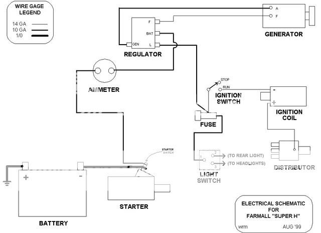
I think I have a problem with the wiring of the Cub. I replaced all wires, one for one, but the arrangment is not quite the same as is shown in my Operators manuals. The manual shows an "L" terminal on the voltage regulator, but my VR has none. My VR "F" is not connected to the generator "F".
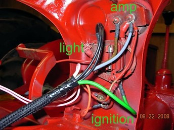
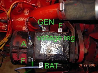
My grey wire from VR "BAT" goes to the ammeter. My green wire from generator "F" goes to (not sure - looks like below light switch). brown wire runs between ammeter and starting switch; orange wire runs from ignition switch to coil; black wire runs from light switch to headlights.
a747.jpg
 
Michael, we gotta so some diagnostic work, here goes:

1) Its possible to use a 3 terminal (BAT ARM FLD) VR where a 4 terminal (BAT ARM FLD LOAD) was original equipment. Later.......

2) On some 4 terminal VR"s the ARM terminal is UNDERNEATH and BAT FLD LOAD are up on top...TAKE A GOOD LOOK AT YOUR VR (look underneath for any terminals) TO BE SURE WHAT IT IS AND IF ANY TERMINALS ARE LABELED.

3) WIRING: On tractors intened for 4 terminal VR"s (they had LOAD terminal) the hot voltage BAT input to the light switch was fed from the LOAD terminal on a 4 terminal VR......HOWEVER if a 3 terminal VR was used (no L terminal) the hot voltage input to the light switch was fed from the ammeters load (NOT battery/starter) terminal, same terminal that wired down to BAT on the VR.

4) To use a 3 terminal VR where a 4 was before, simply feed hot batery voltage to the light switches input from the ammeter instead of any L terminal as on a 4 terminal VR

5) WIRING GENNY AND VR:

BAT to load side of ammeter
ARM/GEN to gennys ARM post
FLD on VR to gennys FLD post

If its a 4 terminal with LOAD terminal that feeds hot battery input voltage up to the light switch VERSUS it being fed from the ammeter as on 3 terminal VR systems.

SUMMARY: You gotta first insure if you have 3 or 4 terminal VR and check for labels on terminals (look underneath for any ARM terminal),,,,,,,,,,,,,,,if its only a 3 terminal VR, wire it as posted above and feed light switch off ammeter load (one to BAT on VR) terminal,,,,,,,,,,,,,if its a 4 terminal VR wire as above and feed light switch from LOAD on VR,,,,,,,

Its quite possible its only a 3 terminal VR and if so wire it per the above and/or Bob M"s diagrams.

Let us know

John T
 
It's a cut-out not a regulator. It's controlled through the light switch. The first two position of the light switch are Low and High charge. It's a manual version of a voltage regulator.
 
Wow! Bob's diagrams are terrific. His #3is just what I have. So, until I look beneath my VR (which seems to be a cutout relay - CR) I will be happy that my wiring is accurate. I will check once more; however, I have the four position switch even labeled LHDB [what do the letters mean?] and it was and is again wired as he shows in his #3 diagram.
If I removed my CR, turned it around and re-attached it, my Cub would be the same as Bob's diagram.
Thank you again, Cub Gurus
 
A regular VR either 4 pole, or 3 pole has a cutout relay inside it. I will bet yours is being used as a cutout relay, and can continue to do so wired as it is. The field terminal would be unused, as would an internal component, but the cutout portion would work OK. The light SW is (from full CCW) Low charge High Charge, Dim, Bright LHDB.
There are two parts to the switch one to control the lights, the other is a grounding system for the F terminal of the gen. Do not cross them up, or things will not work. JimN
 
Yo Jim, the one IHC thing I never fully understood is SOME of those actual "Cutout Relays" that wired same as the regular 2 terminal (BAT GEN) cutout relays and still had the gennys FLD post wired to a LHBD switch, STILL HAD AN F TERMINAL ON THEM THAT WASNT USED..........

Isnt that correct, werent some cutout relays equipped with an unused F terminal?????

If so whats that all about????

You or our friend Bob M may have explained this before but I done forgot it grrrrrrrr

John T
 
Your pic appears like its a cut-out and there needs to be a wire from the F on the cut-out to the F post on the gen. The wire going from the F term on the cut-out goes to the four step sw to the bottom terminal that has a resistor which is flat looking. This will provide hi-charge when it is switched to the second position. I have several of these type cut-out gen combination on my As and B model and thats the way they are supposed to be wired. Your cut-out will only have three connections Batt, Gen and Field. If it has more connections it is not a cut-out. Your generator mite have the three brush adjustable for the amount of charge rate.
 
The letter "L"stands for low charge which means with the switch in that position the resistor is in line from generator "F" to ground and generator charges a lower amount. The letter "H" stands for high charge which means in that position the "F" wire from generator goes straight to ground which makes the generator charge at maximum. The letter "D" is for headlights on dim and the letter "B" is for headlights on bright.......Gale
 
I have never seen a F terminal on a CO that was stock on an IH/Farmall. (that does not mean all that much)
But IH was pretty good about not buying what it did not need.
I need to ad to the above discussion that the Light switch will also be at full charge F grounded through the switch)on both D and B positions for lights. Jim
 
(quoted from post at 05:54:50 08/24/08 ) I have never seen a F terminal on a CO that was stock on an IH/Farmall. (that does not mean all that much)
The cut-outs that IH used DID have an "F" terminal. It usually wasn't used. If a tractor was equipped with electric starting but no lights (a legitimate combination) the "F" terminal of the cut-out was used. (With no lights, there was no light switch!).
 

We sell tractor parts! We have the parts you need to repair your tractor - the right parts. Our low prices and years of research make us your best choice when you need parts. Shop Online Today.

Back
Top